Hierarchically structured mass storage device and method

a mass storage device and hierarchy structure technology, applied in the field of computer memory systems, can solve the problems of low performance, low price of ultra-high capacity storage, and high cost compared to nand flash, and achieve the effects of reducing access times and write endurance, high write endurance, and fast access times

Inactive Publication Date: 2010-12-23
OCZ STORAGE SOLUTIONS
View PDF6 Cites 116 Cited by
  • Summary
  • Abstract
  • Description
  • Claims
  • Application Information

AI Technical Summary

Benefits of technology

[0009]The current invention provides a computer mass storage system comprising multi-tiered hierarchical-ordered non-volatile memory, which is in addition to a volatile cache of the type common to conventional HDDs and SSDs. The invention preferably makes use of hierarchical storage management (HSM) algorithms, which can be used to identify high frequency access patterns, the target files of which are then moved into a higher-speed, higher-endurance tier within the multi-tiered hierarchical-ordered non-volatile memory.
[0010]According to a first aspect of the invention, a mass storage system includes a mass storage memory drive, a control logic on the mass storage memory drive and configured to execute a hierarchical storage management technique, a volatile memory cache configured to be accessed by the control logic, and first and second non-volatile storage arrays on the mass storage memory drive and comprising, respectively, first and second non-volatile memory devices. The first and second non-volatile memory devices have properties including access times and write endurance, and at least one of the access time and the write endurance of the first non-volatile memory devices is faster or higher, respectively, than the second non-volatile memory devices.
[0011]According to a second aspect of the invention, a method of using the mass storage system includes operating the control logic to execute hierarchical storage management using the first and second non-volatile storage arrays to store data, including determining through an access pattern a locality on one of the first and second non-volatile storage arrays for storing the data thereon by utilizing the properties of the first and second non-volatile storage arrays to match storage requirements of the data. The data are then written to the locality on the first or second non-volatile storage array.
[0012]From the above, it can be appreciated that the first and second non-volatile storage arrays are effectively separate tiers of mass storage devices within the mass storage system. Preferred non-volatile memory devices for the first non-volatile storage array include, but are not limited to, solid-state memory devices such as phase change memory, nV SRAM, ferromagnetic memory (for example, FRAM), or any other suitable non-volatile memory characterized by relatively fast access times and high write endurances. The second non-volatile storage array can constitute a large array of non-volatile memory devices with relatively lower access times and write endurances and lower cost per bit, notable examples of which include solid-state memory devices such as flash memory in either NAND or NOR variation. An access monitoring circuitry captures the addresses and counts the frequency of all requests. If the number of requests for a specific set of data over a predetermined period of time exceeds a threshold, the data are copied from the second non-volatile storage array into the first non-volatile storage array. If the data in the first non-volatile storage array are modified, the modified data are preferably written back to the second non-volatile storage array. On the other hand, if the data are not modified and the access frequency drops below the threshold, the data can simply be invalidated and the next request will go back to the second non-volatile storage array. Alternatively, the data can be written back to the second non-volatile storage array upon expiration of the priority level.

Problems solved by technology

On the back end of archives, tape drives, and particularly digital linear tapes (DLT), have provided ultra-high capacity storage at low price and low performance.
FRAM and PCM are currently the farthest along with respect to maturity, write endurance, speed and density, but compared to NAND flash the cost is still orders of magnitude higher.
However, the currently employed form of caching is limited by the comparably very small amount of memory and, in addition, the cached data are not permanent but subject to maintenance of power to the device.
Though SSDs are starting to replace HDDs in current computer systems, like any other NAND-based device, they have limited data retention and write endurance.
However, in practice, two issues artificially inflate the number of writes.
Firstly, NAND flash cannot be overwritten since bit changes can only occur from 1 to 0 but not the other way.
Secondly, the static mapping of memory pages within each NAND flash block causes rewriting of every block's content with any file update, which increases the number of actually written and erased bytes orders of magnitude over the number of byte updates needed.
The combination of both factors increases the wear on NAND memory devices and also causes some significant slowing of SSDs once they start filling up with orphaned data that are simply unmanaged leftovers from previous updates without any pointers associated with them.
This does not, however, solve the fundamental problem of limited write endurance and data retention as a cause of proximity write and read disturbance.
Particularly those updates of small files, which include housekeeping of the operating system, add a substantial amount of stress to a NAND flash-based drive because each update requires a complete rewriting of a larger set of data, very often an entire block.

Method used


Image

  • Hierarchically structured mass storage device and method
  • Hierarchically structured mass storage device and method
  • Hierarchically structured mass storage device and method

Examples


Embodiment Construction

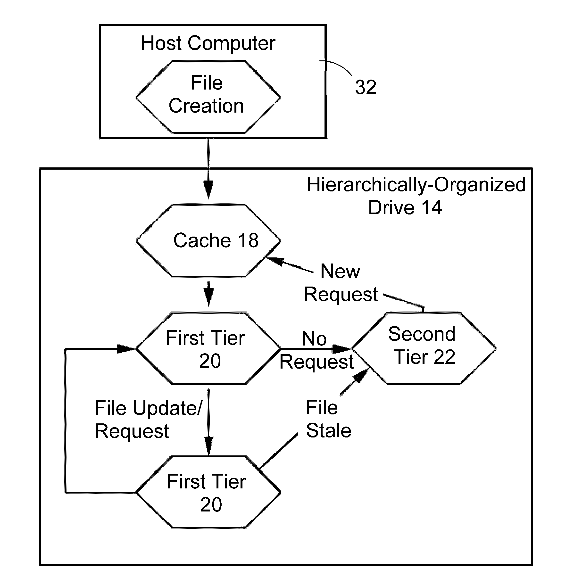
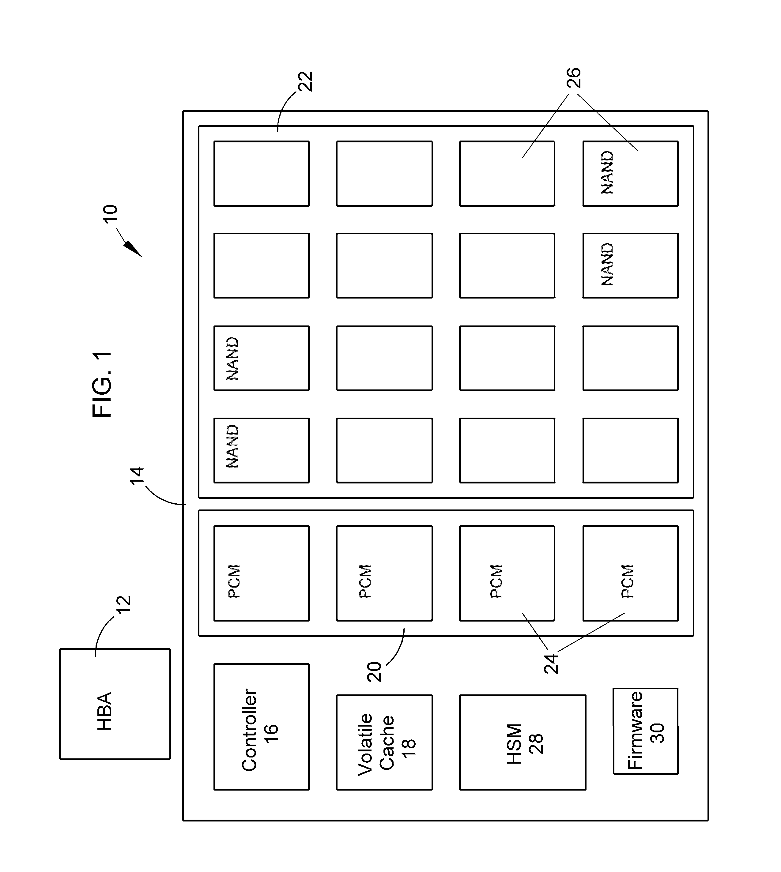
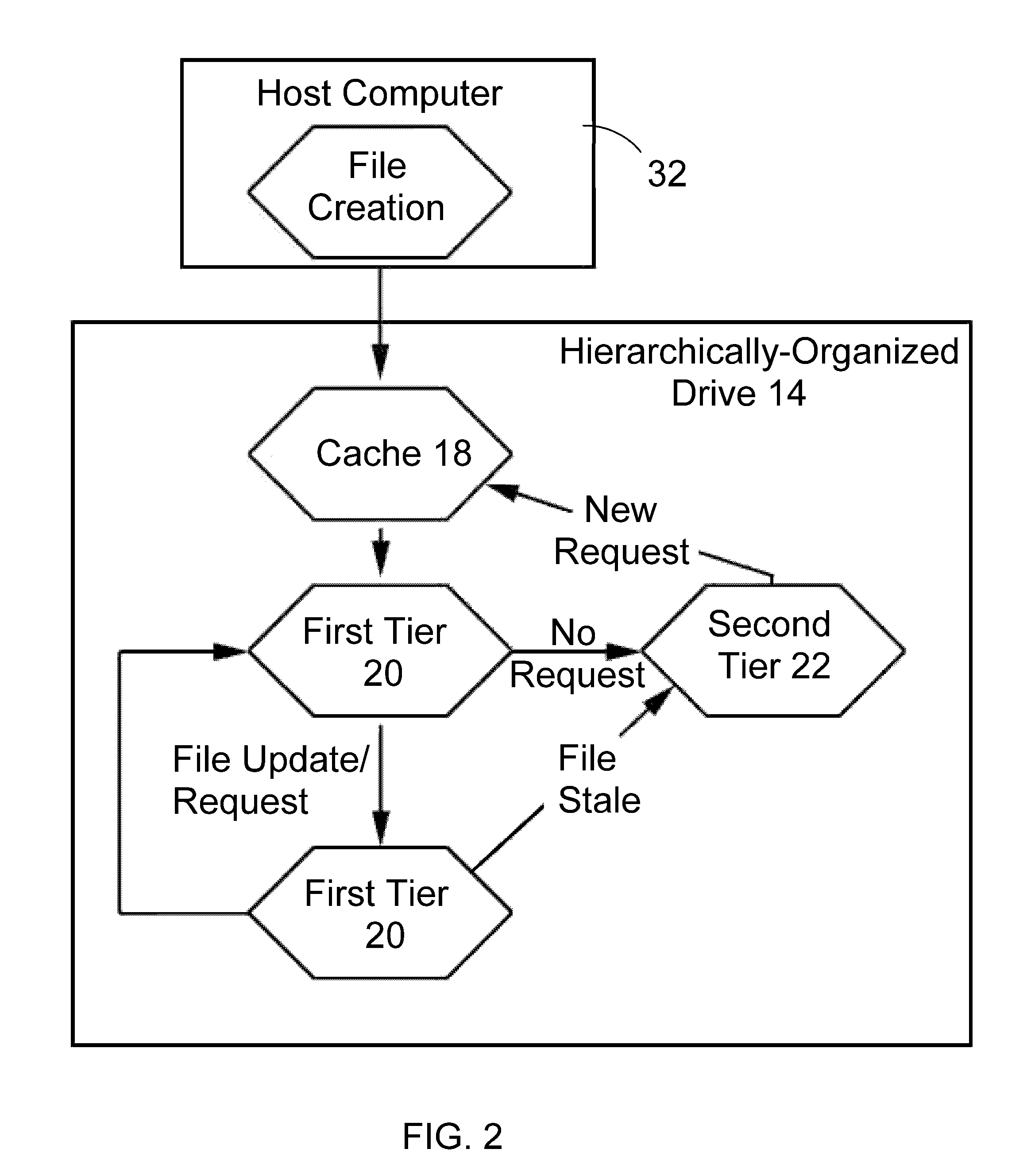
[0018]FIG. 1 schematically represents a hierarchically-organized mass storage system 10 suitable for use in a computer in accordance with an embodiment of the invention. A host bus adapter (HBA) 12 of the computer is represented as being adapted to interact with control logic on a non-volatile mass storage memory device, referred to herein as a drive 14. The control logic includes a controller 16 configured to access a volatile cache 18 and multiple discreet domains or tiers of memory, represented in FIG. 1 by first and second tiers 20 and 22 of memory containing arrays of non-volatile memory devices 24 and 26, respectively, on the drive 14. Memory technologies used within the tiers 20 and 22 are preferably solid-state memory devices, though other technologies are also possible, for example, microelectromechanical systems-based solutions and nanoelectromechanical systems. The non-volatile memory devices 24 and 26 of the tiers 20 and 22 are preferably different, such that the non-vol...


PUM


Abstract

A hierarchically-structured computer mass storage system and method. The mass storage system includes a mass storage memory drive, control logic on the mass storage memory drive that includes a controller and one or more devices for executing a hierarchical storage management technique, a volatile memory cache configured to be accessed by the control logic, and first and second non-volatile storage arrays on the mass storage memory drive and comprising, respectively, first and second non-volatile memory devices. The first and second non-volatile memory devices have properties including access times and write endurance, and at least one of the access time and the write endurance of the first non-volatile memory devices is faster or higher, respectively, than the second non-volatile memory devices. Desired data storage localities on the storage arrays are determined through access patterns and selectively utilizing the properties of the memory devices to match the data storage requirements.

Description

CROSS REFERENCE TO RELATED APPLICATIONS[0001]This application claims the benefit of U.S. Provisional Application No. 61 / 218,571, filed Jun. 19, 2009, the contents of which are incorporated herein by reference.BACKGROUND OF THE INVENTION[0002]The present invention generally relates to computer memory systems, and more particularly to a computer memory system comprising multi-tiered non-volatile memory in a hierarchical order.[0003]Computer system memory systems are generally considered to include caches, volatile high speed memory and non-volatile mass storage memory. In most cases, the non-volatile mass storage memory is in the form of hard disk drives (HDD), comprising magnetic platters mounted on a spindle whereon data are accessed by positioning a read-write head over the logical block address consisting of a sector address and a track. On the back end of archives, tape drives, and particularly digital linear tapes (DLT), have provided ultra-high capacity storage at low price and...

Claims


Application Information

Patent Timeline
Patent Type & Authority Applications(United States)
IPC IPC(8): G06F12/02G06F12/08G06F13/00
CPCG06F3/0613G06F3/0616G06F3/0647G06F3/0685G06F3/0688G06F2212/7202G06F12/08G06F12/0866G06F2212/214G06F2212/463G06F12/0246
Inventor SCHUETTE, FRANZ MICHAELALLEN, WILLIAM J.
Owner OCZ STORAGE SOLUTIONS
Why Eureka
Try Eureka