Dynamic solid state diffractive optics applied for reading a diffractive optics memory

a technology of diffractive optics and dynamic solid state, applied in the field of diffractive optics memory, can solve the problems of slow addressing system of these previous devices, mechanical components of these previous devices need frequent maintenance to correct errors and dysfunction, and place a limit on the ability to miniaturize these systems, etc., to achieve the effect of reducing cost, reducing maintenance costs, and fast access tim

Inactive Publication Date: 2007-05-01
RES INVESTMENT NETWORK
View PDF11 Cites 3 Cited by
  • Summary
  • Abstract
  • Description
  • Claims
  • Application Information

AI Technical Summary

Benefits of technology

[0020]The present invention thus achieves the objectives of fast access time, long life duration, miniaturization, reliability, stability, a limited response to surrounding perturbations, and a lower cost through mass production.

Problems solved by technology

Previous holographic devices for recording information in a highly multiplexed volume holographic memory, and for reading the information out, require components and dimensions having a large size which places a limit on the ability to miniaturize these systems.
Because previous holographic devices use motors and large-scale components such as mirrors and lenses, the addressing systems of these previous devices are slow.
Furthermore, the mechanical components of these previous devices need frequent maintenance to correct errors and dysfunction coming, for instance, from wear and friction (i.e., tribology effect).
Furthermore, previous addressing systems are expensive because they use complex systems for control.
Thus, their prices cannot be lowered by mass production.
Moreover, previous devices are not economical in their energy consumption.
Even when previous addressing devices are accurate when new, the wear and friction of the interacting surfaces that are in relative motion lowers their accuracy with time.

Method used


Image

  • Dynamic solid state diffractive optics applied for reading a diffractive optics memory
  • Dynamic solid state diffractive optics applied for reading a diffractive optics memory
  • Dynamic solid state diffractive optics applied for reading a diffractive optics memory

Examples


Embodiment Construction

Recording Process

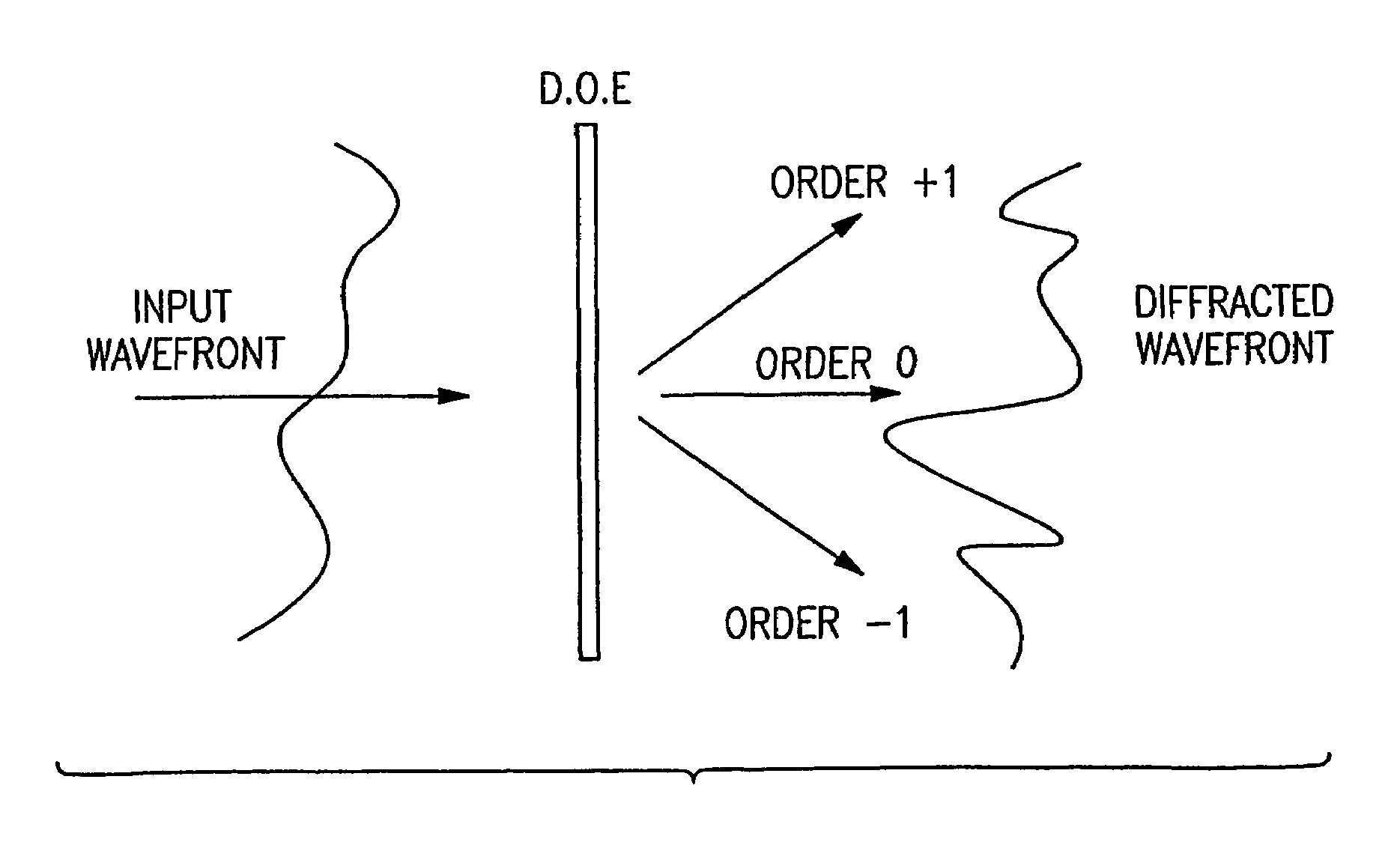
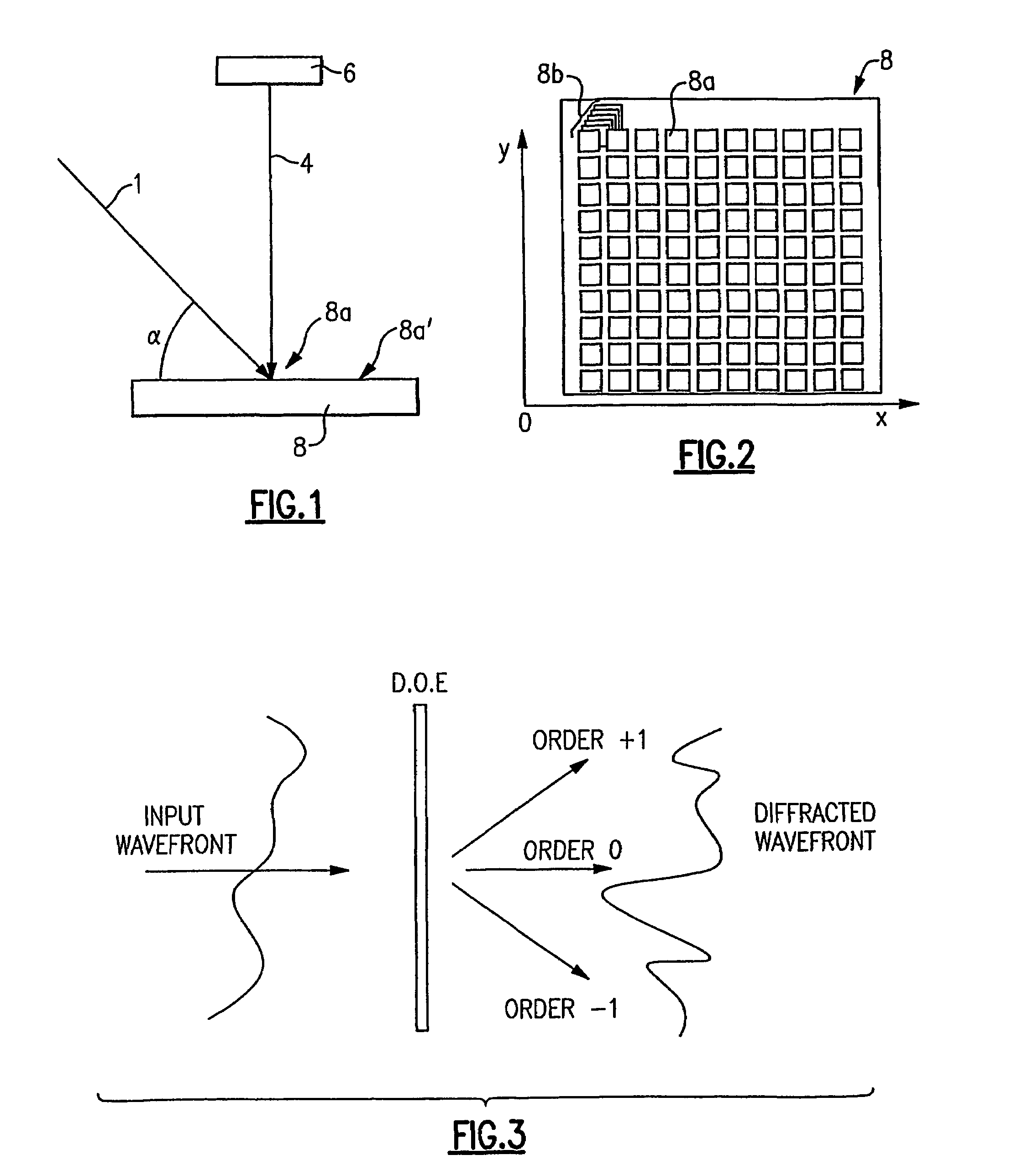
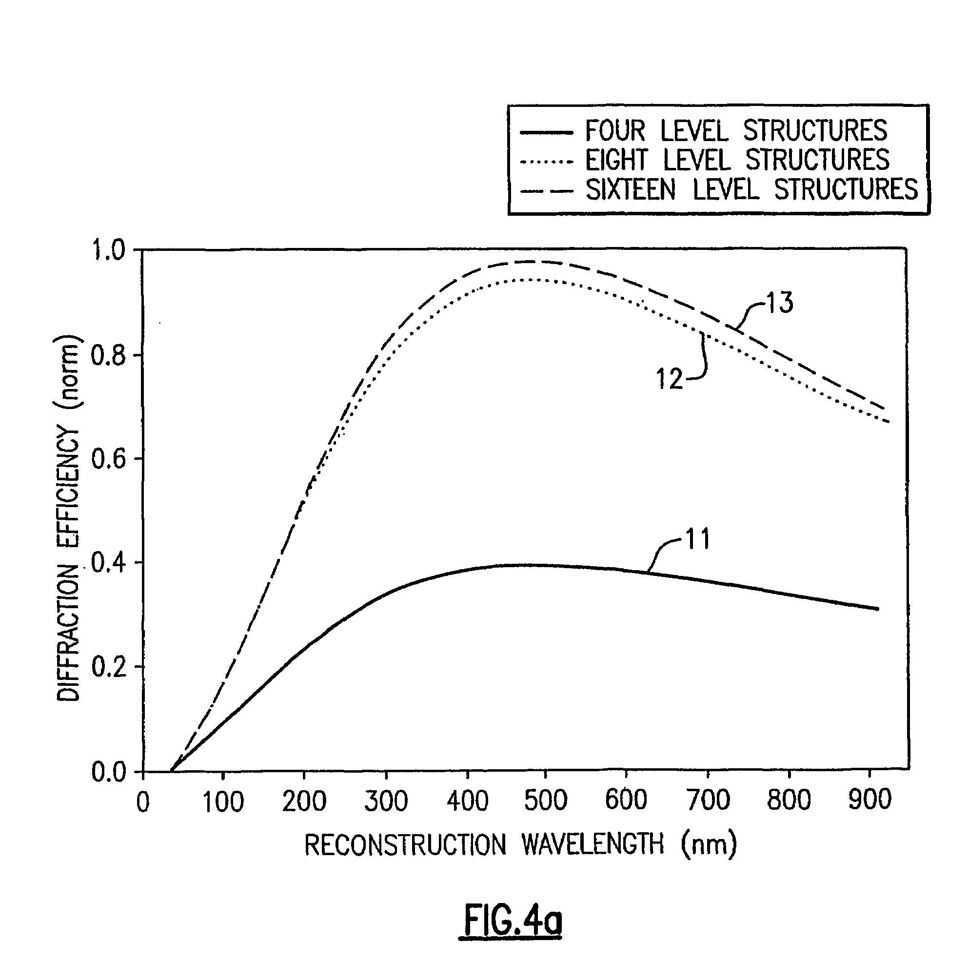
[0044]FIG. 1 shows a schematic of the important signals involved in recording a diffraction pattern, or alternately a hologram, in a storage medium using angular and spatial multiplexing. Various diffractive recording processes have been developed in the art and further details can be found in the book Holographic Data Storage, Springer (2000) edited by H. J. Coufal, D. Psaltis, and G. T. Sincerbox. In this specification, the term “diffractive” is used throughout to differentiate prior art holographic technology used for 3-D image generation from diffractive technology necessary for the generation of a storage medium. For example, diffraction efficiency is critical to the viability of any material to be used as a diffractive storage medium. The quality of interference constituting a 3D-hologram is simple to achieve compared to the quality required to realize a storage medium. Moreover, a storage diffractive pattern can also be implemented by using other techniques t...


PUM

PropertyMeasurementUnit
angleaaaaaaaaaa
geometrical distanceaaaaaaaaaa
sizeaaaaaaaaaa

Abstract

The apparatus and method of the present invention employ solid state dynamic diffractive optical elements for reading information from a diffractive optics memory. The diffractive optics memory has stored therein information located at a plurality of points of the memory and at a plurality of angles at each one of the points so as to form a plurality of packets of information at each of the points. A matrix of the dynamic diffractive optical elements is configured to shape a laser beam to address the memory at one of the angles of one of the points to reconstruct one of the packets of information.

Description

FIELD OF INVENTION[0001]The present invention generally relates to a diffractive optics memory. In particular, the present invention relates to an apparatus for reading information from the diffractive optics memory using dynamic solid state diffractive optics devices.BACKGROUND OF THE INVENTION[0002]The large storage capacities and relative low costs of CD-ROMS and DVDs have created an even greater demand for still larger and cheaper optical storage media. Holographic memories have been proposed to supersede the optical disc as a high-capacity digital storage medium. The high density and speed of the holographic memory comes from three-dimensional recording and from the simultaneous readout of an entire packet of data at one time. The principal advantages of holographic memory are a higher information density (1011 bits per square centimeter or more), a short random access time (˜100 microseconds and less), and a high information transmission rate (109 bit / sec).[0003]In holographic...

Claims


Application Information

Patent Timeline
Patent Type & Authority Patents(United States)
IPC IPC(8): G06K7/10G11B7/0065G11B7/135
CPCG11B7/0065G11B7/1353G11B7/1362G03H2225/24
Inventor KIEFER, RENAUDEL HAFIDI, IDRISSGRZYMALA, ROMUALDAMEYRUEIS, PATRICK
Owner RES INVESTMENT NETWORK
Why Eureka
Try Eureka