Brushless motor

Inactive Publication Date: 2009-05-21
HONDA MOTOR CO LTD
View PDF7 Cites 37 Cited by
  • Summary
  • Abstract
  • Description
  • Claims
  • Application Information

AI Technical Summary

Benefits of technology

[0010]In this case, the holding portion is formed in the coil bobbin. Therefore, the winding finishing end of the coil wound around the winding portion is wound around the holding portion. Thereby, since the coil can be more firmly wound compared with a case where the winding finishing end of the coil is directly connected in the termin

Problems solved by technology

That is, useless space may be created in a portion more radially outside than the through-hole, and accordingly, the wall thickness of the stator core should be made large.
Thus, there is a

Method used


Image

  • Brushless motor
  • Brushless motor
  • Brushless motor

Examples


Embodiment Construction

[0015]Next, an embodiment of the invention will be described with reference to the drawings.

[0016]In the following description, the left side of FIG. 1 is defined as the front side (other end side), and the right side of FIG. 1 is defined as the rear side (one end side).

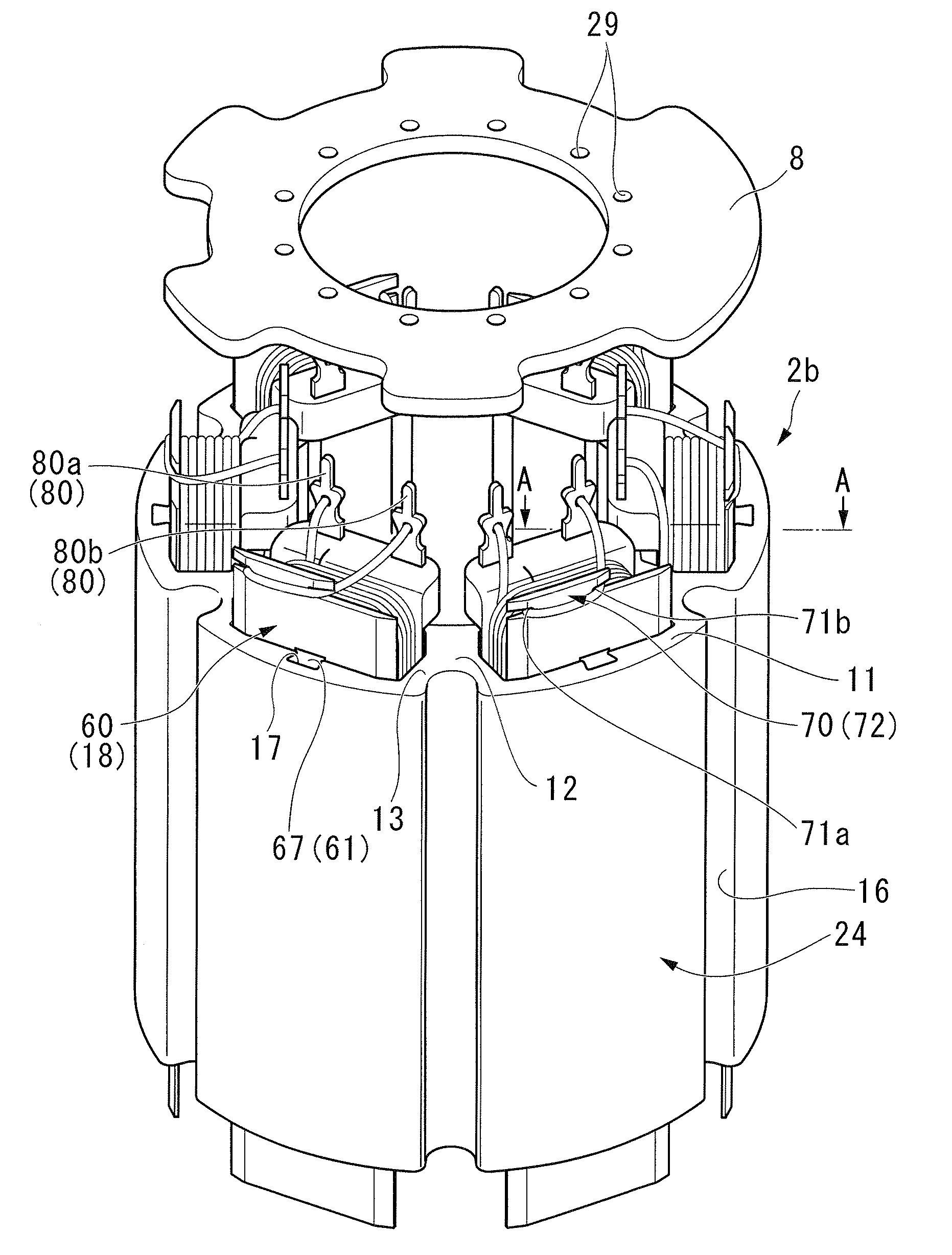
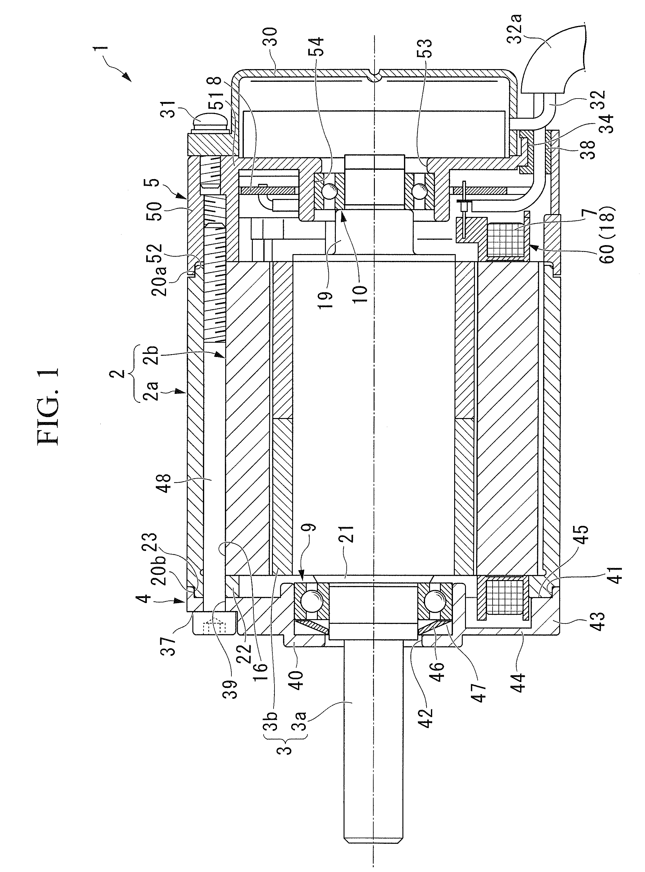
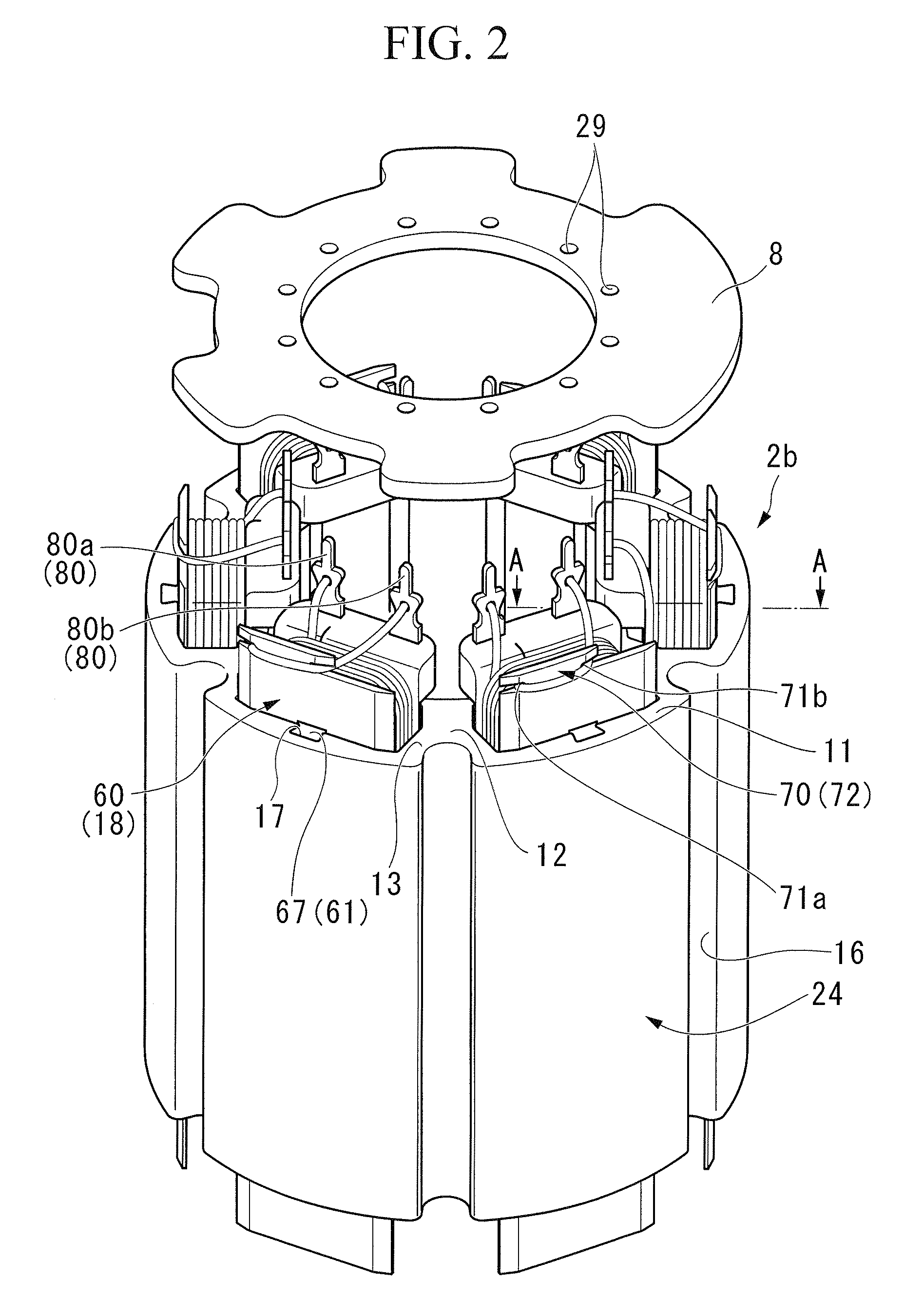
[0017]As shown in FIGS. 1 to 3, a brushless motor 1 of this embodiment is an inner rotor type brushless motor 1, and includes a substantially cylindrical stator 2, and a rotor 3 rotatably provided inside the stator 2.

[0018]The stator 2 includes a substantially cylindrical stator case 2a, and a stator core 2b fitted into and fixed to the stator case 2a.

[0019]The stator core 2b is formed by laminating a magnetic sheet material axially or pressing magnetic metal powder, and includes a tubular yoke portion 11. At an inner peripheral surface of the yoke portion 11, six commutating-pole teeth 12 which protrude radially inward are integrally formed at equal intervals in the peripheral direction of the yoke portion 11.

[0020...


PUM


Abstract

This brushless motor according to the present invention is provided with: a tubular stator case; a stator core; a rotore; a plurality of teeth which are integrally formed on an inner peripheral surface of the stator core; a coil bobbin mounted between the mutually adjacent teeth, which has a winding portion around which a coil is wound; a lead wire; and a wiring substrate which relays a connection between the lead wire and the coil, wherein: the coil bobbin has flange portions; one of the flange portions which is located on the inward in the radial direction has an enlarged member which protrudes outward from the surface of the flange portion; a pair of terminals which is connected to the wiring substrate is provided on the enlarged portion so as to be located more inward than a tip of the tooth in the radial direction.

Description

BACKGROUND OF THE INVENTION[0001]Priority is claimed on Japanese Patent Application No. 2007-287863, filed on Nov. 5, 2007, the contents of which are incorporated herein by reference.FIELD OF THE INVENTION[0002]The present invention relates to an inner rotor type brushless motor which has, for example, a rotor and a stator.DESCRIPTION OF THE RELATED ART[0003]Generally, an inner rotor type brushless motor has a stator core fitted into and fixed to a stator case, and a rotor rotatably provided with respect to the stator core, and includes permanent magnets at an outer peripheral portion thereof. This stator core includes a plurality of teeth which protrude radially inward. A coil bobbin around which a coil is wound is mounted on each of the teeth. As electric current flows into the coil, an attractive or repulsive force is generated between the rotor and the stator to rotate the rotor.[0004]Among this type of coil bobbin, for example, there is one which is constituted by a connecting ...

Claims


Application Information

Patent Timeline
IPC IPC(8): H02K3/52
CPCH02K2203/03H02K3/522
Inventor YUMOTO, TOHRUISHIDA, HISASHIMIYAZAKI, SUSUMUHAMAYA, KAZUSHI
Owner HONDA MOTOR CO LTD
Why Eureka
Try Eureka