Constant velocity joint

a constant velocity, joint technology, applied in the direction of bearing unit rigid support, couplings, other domestic objects, etc., can solve the problems of fatigue breaking or static breaking of the joint, abrasion of the fitting serration portion or the like, and a lack of nuts, etc., to achieve sufficient quenching hardness, reduce the quenching temperature, and facilitate the effect of carrying ou

Inactive Publication Date: 2009-05-28
NTN CORP
View PDF3 Cites 6 Cited by
  • Summary
  • Abstract
  • Description
  • Claims
  • Application Information

AI Technical Summary

Benefits of technology

[0013]In accordance with the present invention, the constant velocity joint to be connected to a bearing device for wheel support include a joint inner ring, a joint outer ring, and a torque transmitting member for transmitting a rotation. The torque transmitting member is interposed between the joint inner ring and the joint outer ring. The joint outer ring has a cup portion and a stem portion protruding axially outwardly from an outer bottom surface of the cup portion. The stem portion is inserted to a through hole of a hub of the bearing device, and an abutting face abuts to an inboard side end face of bearing inner ring mounted on an outer periphery of the hub being provided in the outer bottom surface. In the constant velocity joint, the joint outer ring is a hot forged product of a steel material, a matrix material portion thereof represents a standard structure, and a part of the outer surface layer thereof represents a non-standard structure. The non-standard structure is any one of an upper bainite structure, a lower bainite structure and a tempered martensite structure, or a mixed structure of at least two or more of those structures. In the non-standard structure, since solution heat treatment can be easily carried out during quenching, it is possible to lower a quenching temperature, to obtain a sufficient quenching hardness and to prevent even a hardening crack. Accordingly, it is possible to reduce the abrasion of the abutment face in the joint outer ring, abutting against the inner ring end face of the bearing device, due to the fretting, the creep of the bearing inner ring 28 or the like. Further, since the non-standard structure is fine in structure and a hardness thereof increased, the strength of the cup portion can increase.

Problems solved by technology

If such abutting end face of the joint outer ring is worn, an axial tension generated by fastening of the nut is lowered, and as a result, a slack of the nut, an abrasion of a fitting serration portion or the like may then take place.
Such great load may cause a fatigue breaking or a static breaking in the joint.
However, the increase of the thickness or the diameter causes an increase of a weight.
Further, the usage of the high strength material causes a reduction of a workability and an increase of manufacturing cost.
The addition of the thermal refining causes a further increase of manufacturing cost.
Also, since a corner portion is formed between the abutting face of the joint outer ring and the cup, the induction heat treatment to the abutting face may cause overheating of the corner portion.
Further, such overheating of the corner portion may cause a quenching crack.

Method used


Image

  • Constant velocity joint
  • Constant velocity joint
  • Constant velocity joint

Examples


Embodiment Construction

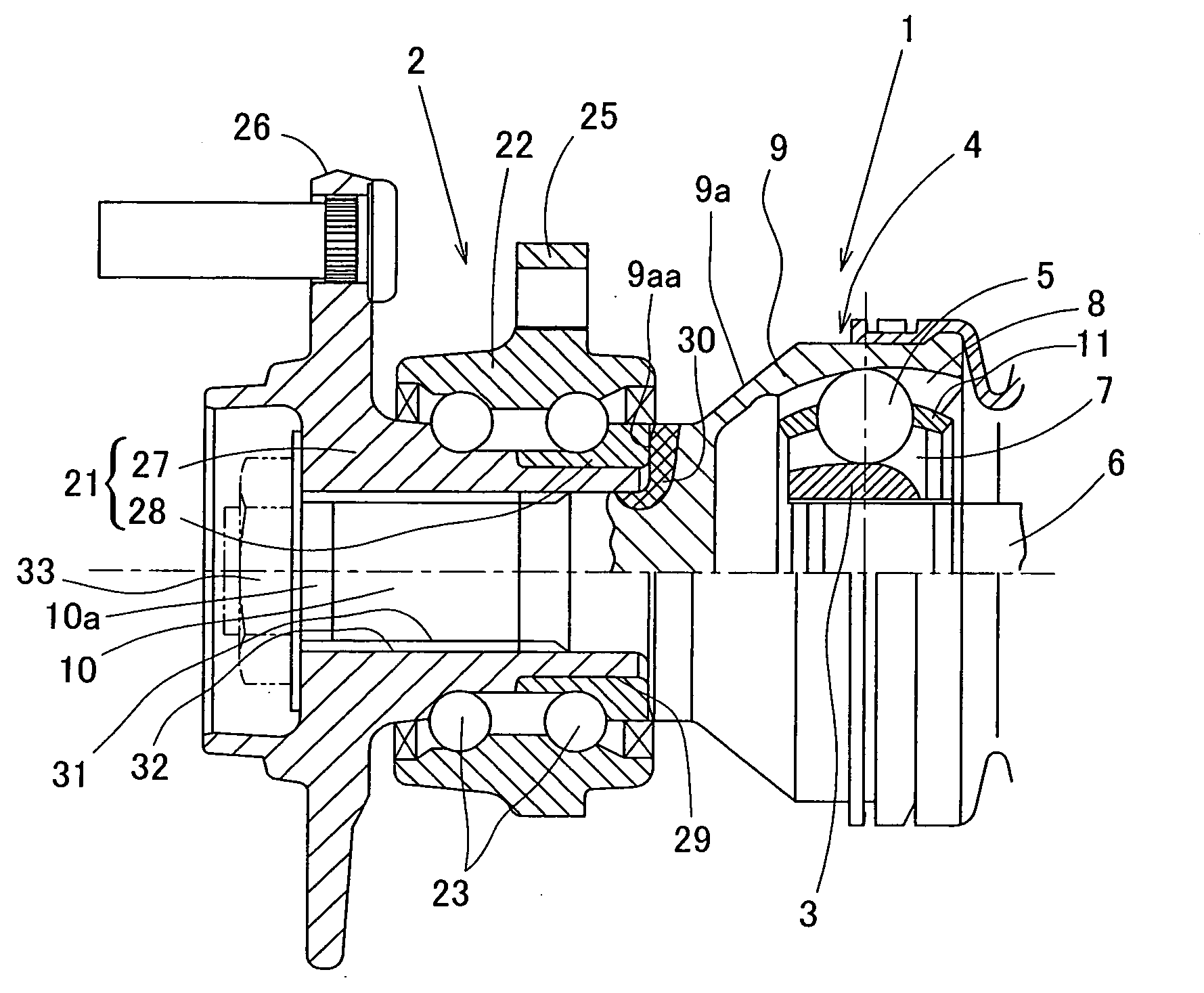
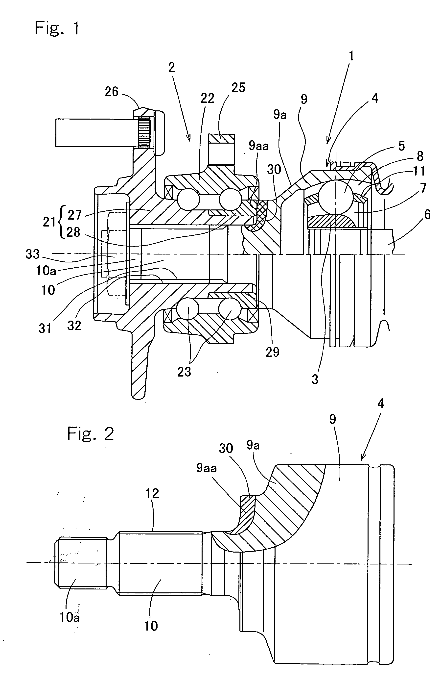
[0021]Hereinafter, an embodiment of the present invention will be described with reference to FIGS. 1 to 5. FIG. 1 is a broken front elevational view of a drive shaft device in which a constant velocity joint and a bearing device for a wheel are coupled. The constant velocity joint 1 includes a joint outer ring 4, a joint inner ring 3 and a torque transmission member 5 interposed between the inner and outer rings 3 and 4. The torque transmission member 5 is formed by a plurality of balls to transmit a rotation between the joint inner ring 3 and the joint outer ring 4. The joint inner ring 3 is fitted to an outer periphery of a shaft 6, and has a spherical outer surface provided with a plurality of track grooves 7 extending along the axial direction. The joint outer ring 4 has a cup portion 9 to accommodate the joint inner ring 3 therein and a stem portion 10 protruding from an outer bottom face 9a provided on the outboard side of the cup portion 9. The cup portion 9 is provided with...


PUM

PropertyMeasurementUnit
temperatureaaaaaaaaaa
operating angleaaaaaaaaaa

Abstract

A joint outer ring (4) of a constant-velocity joint (1) has a stem portion (10) protruding from of a cup portion (9) and inserted to a through hole (31) of a hub (27) in a bearing device (2). The joint outer ring (4) has an abutment face (9aa) abutting against an end face of a bearing inner ring (28) fitted to an outer periphery of the hub (27) in an outer bottom face (9a) of the cup portion, and is composed of a forged product of a steel material. The joint outer ring (4) has a base material portion composed of a standard structure and an outer surface layer partially formed as a non-standard structure portion (30). The non-standard structure may be any one of an upper bainite structure, a lower bainite structure and a tempered martensite structure, or a mixed structure of at least two of the structures.

Description

FIELD OF THE INVENTION[0001]The present invention relates to a constant velocity joint to be coupled to a bearing device for a wheel.BACKGROUND OF THE INVENTION[0002]A wheel support bearing device for supporting a drive wheel is fastened to a joint outer ring of a constant velocity joint by means of a nut, and transmits a driving force to the drive wheel. The joint outer ring of the constant velocity joint abuts against a bearing inner ring. Therefore, there is a case that a bending moment applied to the bearing device and the constant velocity joint during a turn of a motor vehicle causes an abrasion due to a fretting or a creep of the bearing inner ring at an end face of the bearing inner ring and an end face or a back face of the joint outer ring, which is in abutment with the end face of the bearing inner ring. If such abutting end face of the joint outer ring is worn, an axial tension generated by fastening of the nut is lowered, and as a result, a slack of the nut, an abrasion...

Claims


Application Information

Patent Timeline
Patent Type & Authority Applications(United States)
IPC IPC(8): F16D3/20
CPCB21K1/40B21K1/762B21K1/765F16D2250/00F16D3/223F16D3/845F16D2003/22326C21D8/00F16C19/184F16C19/186F16C35/0635F16C2326/02F16D2250/0053Y10S72/714Y10S464/906
Inventor HIRAI, ISAOYOSHIDA, KAZUHIKO
Owner NTN CORP
Why Eureka
Try Eureka