Dosimetry device for verification of a radiation therapy apparatus

a radiation therapy apparatus and dosimetry technology, applied in the direction of photometry, electrodes and associated parts, radiation therapy, etc., can solve the problems of large change in clinical response, difficult to achieve accurate and consistent treatment, and steep response curves

Active Publication Date: 2009-08-13
ION BEAM APPL +2
View PDF5 Cites 16 Cited by
  • Summary
  • Abstract
  • Description
  • Claims
  • Application Information

AI Technical Summary

Benefits of technology

[0039]In another preferred embodiment of the method according to the second aspect of the invention, said step of providing a dosimetry device comprising three or more lines of radiation detectors, said lines being parallel to each other, and perpendicular to the leaf travel direction, radiation detectors on said lines being located under the projection of leaves of said MLC, thereby allowing the simultaneous determination of the positions and / or penumbrae of a plurality of leaves.

Problems solved by technology

Moreover, for some tumours and normal tissues, the dose response curves may be very steep in the therapeutic dose range, i.e., a small change in dose can result in a large change in clinical response.
Delivery of treatment in an accurate and consistent manner is by no means easy to achieve, since the radiation therapy process is a complex interweaving of a number of related tasks for designing and delivering radiation treatments.
Although this device represents the golden standard in accelerator commissioning, acceptance and routine QA, thanks to its flexibility in recording the dose profiles, performing the needed measurements with it is a cumbersome and long lasting task: the water tank is a heavy and bulky device and takes long to set it up; the scans take time to be performed as normally only one detector is present, etc.
However, the main problem of these devices is the fact that they use diodes which have a non-linear response to dose, requiring accordingly complex calibration methods such as the one described in document U.S. Pat. No. 6,125,335.
Furthermore, compared to dosimetry equipments based on ionisation chambers, a device using diodes has a cost price per unit (pixel) higher than a device using ionisation chambers.
Although this device is considered to be very efficient, its geometry, a matrix of 32×32 ionisation chamber pixels, is best adapted to the complexity of the dose distributions delivered in IMRT but well too complex and expensive for standard and conformal RT, where normally only the profiles on the main axis and diagonals are needed.
Furthermore, the complexity of arranging such a high number of detectors and their read-outs in a matrix had an impact on the dimensions of such a device, which is not large enough to cover all the field dimensions which need to be checked both in routine QA and in accelerator commissioning / acceptance.
Therefore, it cannot verify the quality of a radiation field of any size, according to any recommended QA protocol.
However, this device requires a mechanical drive for the sensor, and the measurement is more time-consuming.
No means are provided for measuring radiation beam energy.
A leaf position error increase or decreases the irradiated volume of the detector.
However, no means are provided for measuring other parameters such as the radiation energy.
Accordingly, no practical solution is proposed to perform an easy and fast beam profile and energy measurement with a known device.

Method used


Image

  • Dosimetry device for verification of a radiation therapy apparatus
  • Dosimetry device for verification of a radiation therapy apparatus
  • Dosimetry device for verification of a radiation therapy apparatus

Examples


Embodiment Construction

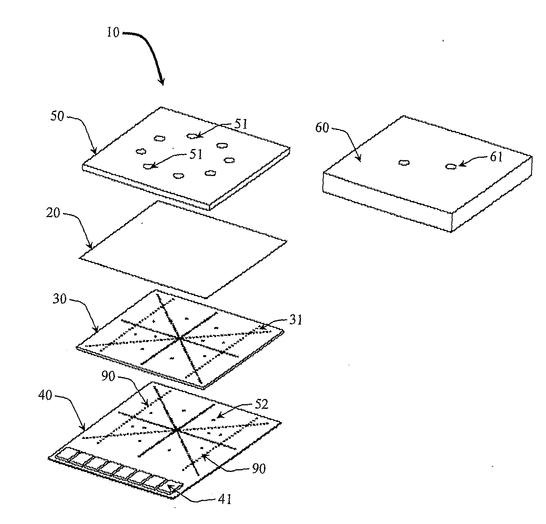
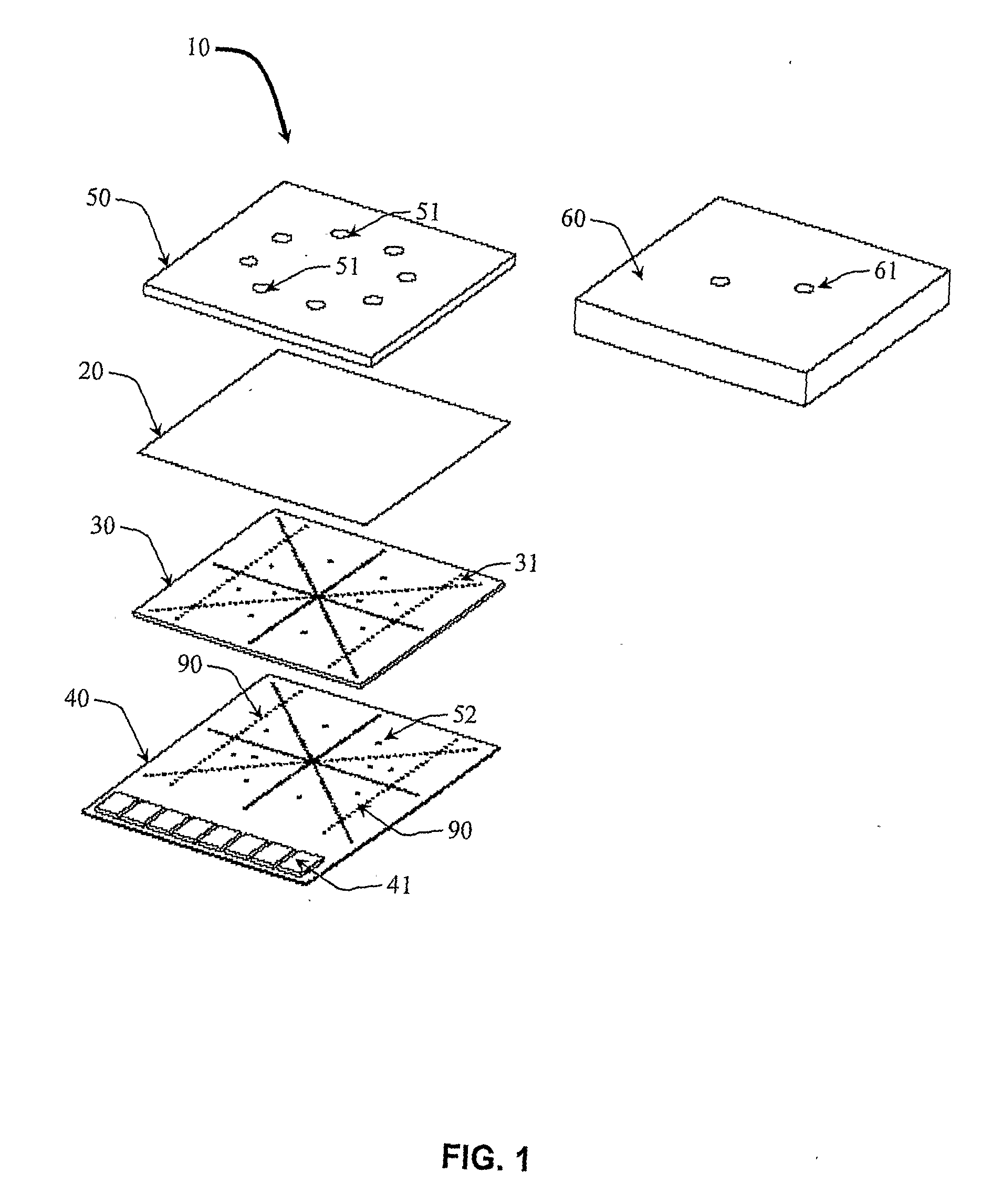
[0047]In relation to the appended drawings, the present invention is described in details for an embodiment using ionisation chamber technology.

[0048]It is apparent however that a person skilled in the art can imagine several other equivalent embodiments or other ways of executing the present invention, such as suggesting diodes instead of ionisation chambers for the radiation detectors, the spirit and the scope of the present invention being limited only by the terms of the claims.

[0049]FIG. 1 represents an exploded view of a device according to a preferred embodiment of the present invention, which is using ionisation chambers in order to perform dosimetry tests. This dosimetry device 10 essentially consists in a stack of three main planar components:[0050]1) a top layer 20, constituting the electrode top layer;[0051]2) a mid layer 30 wherein drilled holes 31 delimit the gas volumes of the ionisation chambers;[0052]3) a bottom layer 40 being the segmented electrode and carrying al...


PUM


Abstract

The present invention relates to a dosimetry device for verification of quality of a radiation beam in standard and conformal radiation therapy, and for IMRT (Intensity Modulated Radiation Therapy) applications. The device includes an active area comprising individual radiation detectors. The active area comprises a limited number of lines of radiation detectors, and a number of extra radiation detectors dedicated to the energy measurement of electrons or photons. It also comprises a build-up plate with energy degraders. The energy degraders are located upstream from the extra radiation detectors in the path of the radiation beam.

Description

FIELD OF THE INVENTION[0001]The present invention is related to a dosimetry device and method allowing accelerator factory testing, commissioning, acceptance and quality assurance (QA) for verification of the quality of the radiation delivery in standard and conformal radiotherapy, as well as partial QA in IMRT (intensity modulated radio therapy) applications and tomotherapy applications.STATE OF THE ART[0002]In treating patients with radiation, the radiation oncologist prescribes a treatment regimen whose goal is to cure or control the disease by precisely delivering an optimal radiation dose to the tumor and reducing the side effects on healthy surrounding tissues. In general, published clinical and experimental results demonstrate that the response of tumours and normal tissues to radiation is highly variable. Moreover, for some tumours and normal tissues, the dose response curves may be very steep in the therapeutic dose range, i.e., a small change in dose can result in a large ...

Claims


Application Information

Patent Timeline
Patent Type & Authority Applications(United States)
IPC IPC(8): G01T1/02G01T1/00
CPCA61N5/1048A61N2005/1076G01T1/185G01T1/14A61N2005/1087A61N5/1075
Inventor BRUSASCO, CATERINAMARCHETTO, FLAVIO
Owner ION BEAM APPL
Why Eureka
Try Eureka