Storable seat for vehicle

a storage seat and vehicle technology, applied in the direction of movable seats, roofs, transportation and packaging, etc., can solve the problems of seat movement not being smooth, position is not stabilized, and the mounting location and dimension errors, so as to prevent an undue load and stable manner

Active Publication Date: 2009-10-01
TOYOTA BOSHOKU KK
View PDF3 Cites 18 Cited by
  • Summary
  • Abstract
  • Description
  • Claims
  • Application Information

AI Technical Summary

Benefits of technology

[0013]By providing the link allowed to undergo positional displacement and another link side by side, it becomes possible to move the seat between the in-use position and the stored position in a more stable manner. In this case, even when there is a relative dimensional error between the link allowed to undergo positional displacement and another link, because one link is allowed to undergo positional displacement, the dimensional error can be absorbed precisely. Hence, it becomes possible to prevent an undue load from being applied on the respective links or the like. In addition, by shaping the another link from two members and making at least one of the fixing holes in the upper and lower link members into a long hole, it becomes possible to adjust the fixing position of the fixing member within the fixing hole when the another link is assembled. It thus becomes possible to adjust the length of the another link at the time of assembly in response to an error in the mounting location of the coupling member.

Problems solved by technology

Respective members, such as the coupling members, each link, a striker to fix the seat, and a hook engaging with the striker, have errors in mounting location and dimension.
This configuration raises problems as follows.
That is, the seat position is not stabilized, the seat cannot be moved smoothly between the in-use position and the stored position, and the respective coupling members and links undergo deformation or break due to an undue load applied thereon.

Method used


Image

  • Storable seat for vehicle
  • Storable seat for vehicle
  • Storable seat for vehicle

Examples


Embodiment Construction

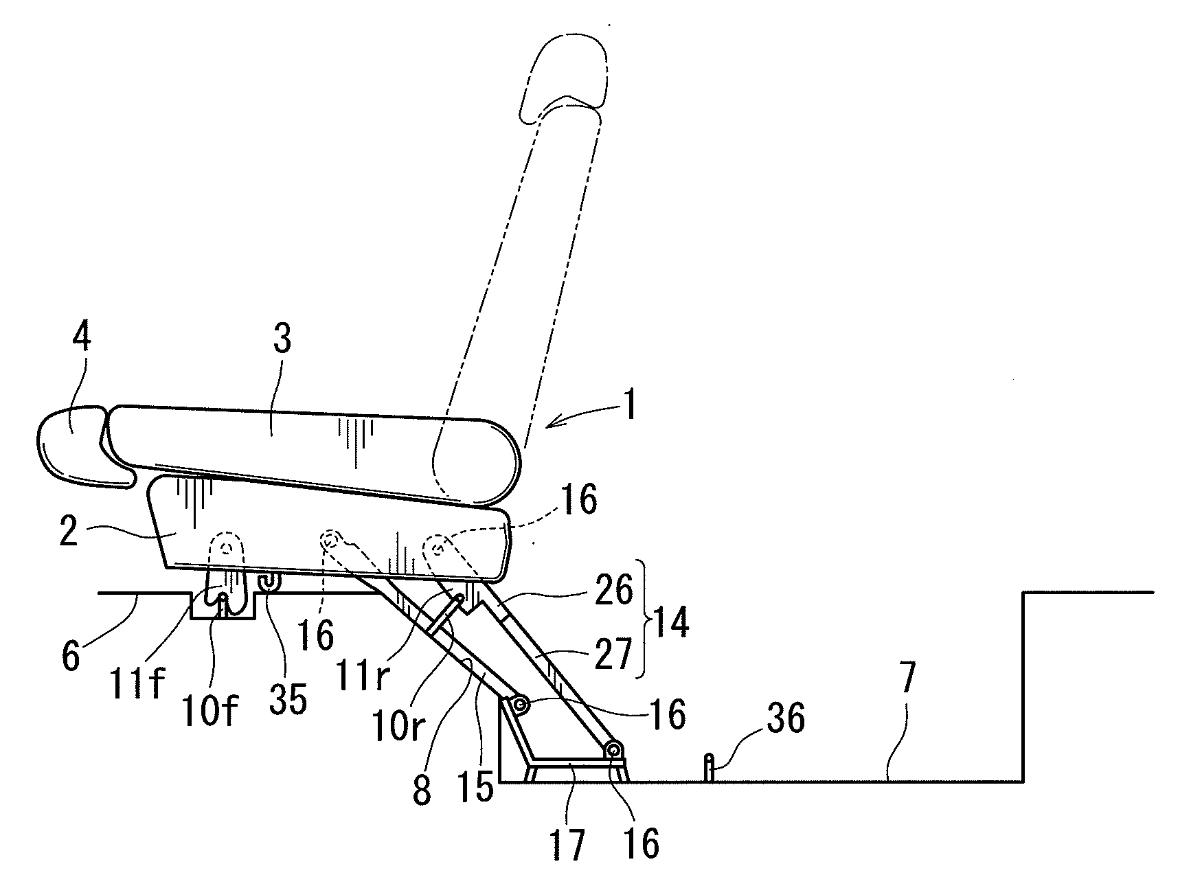
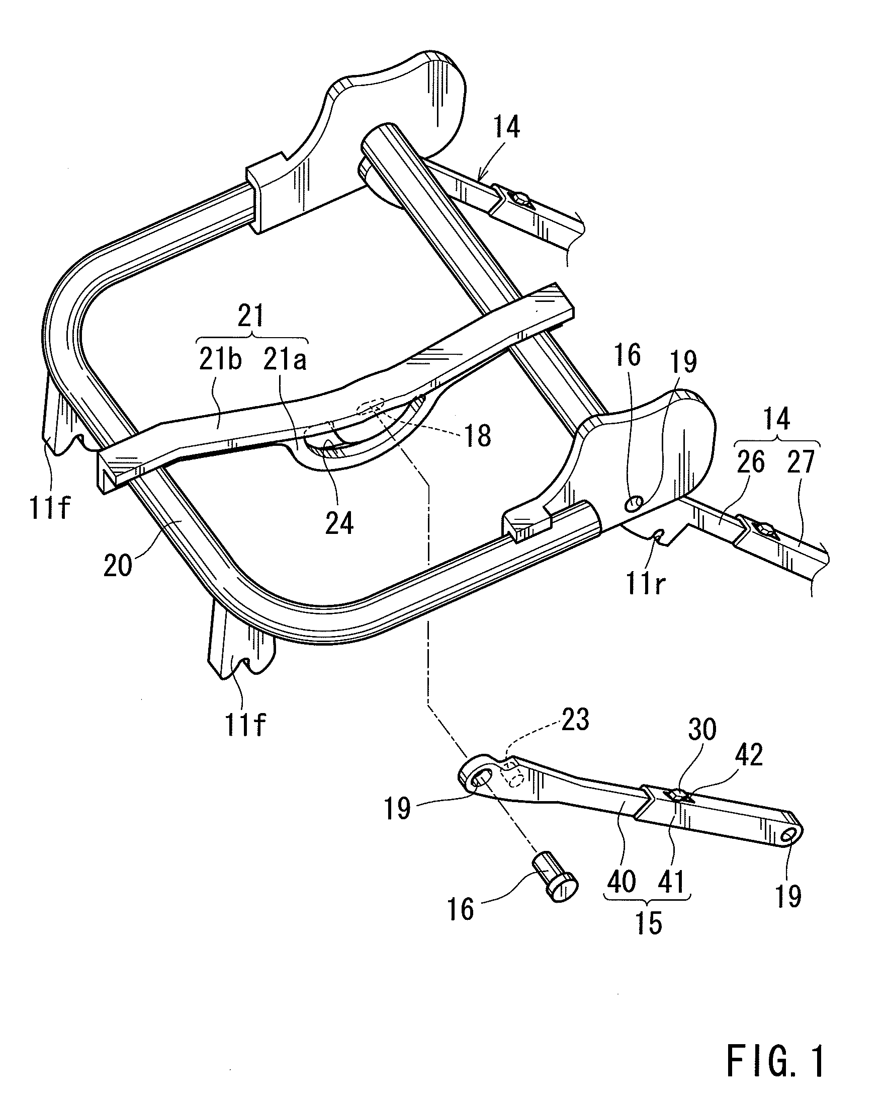
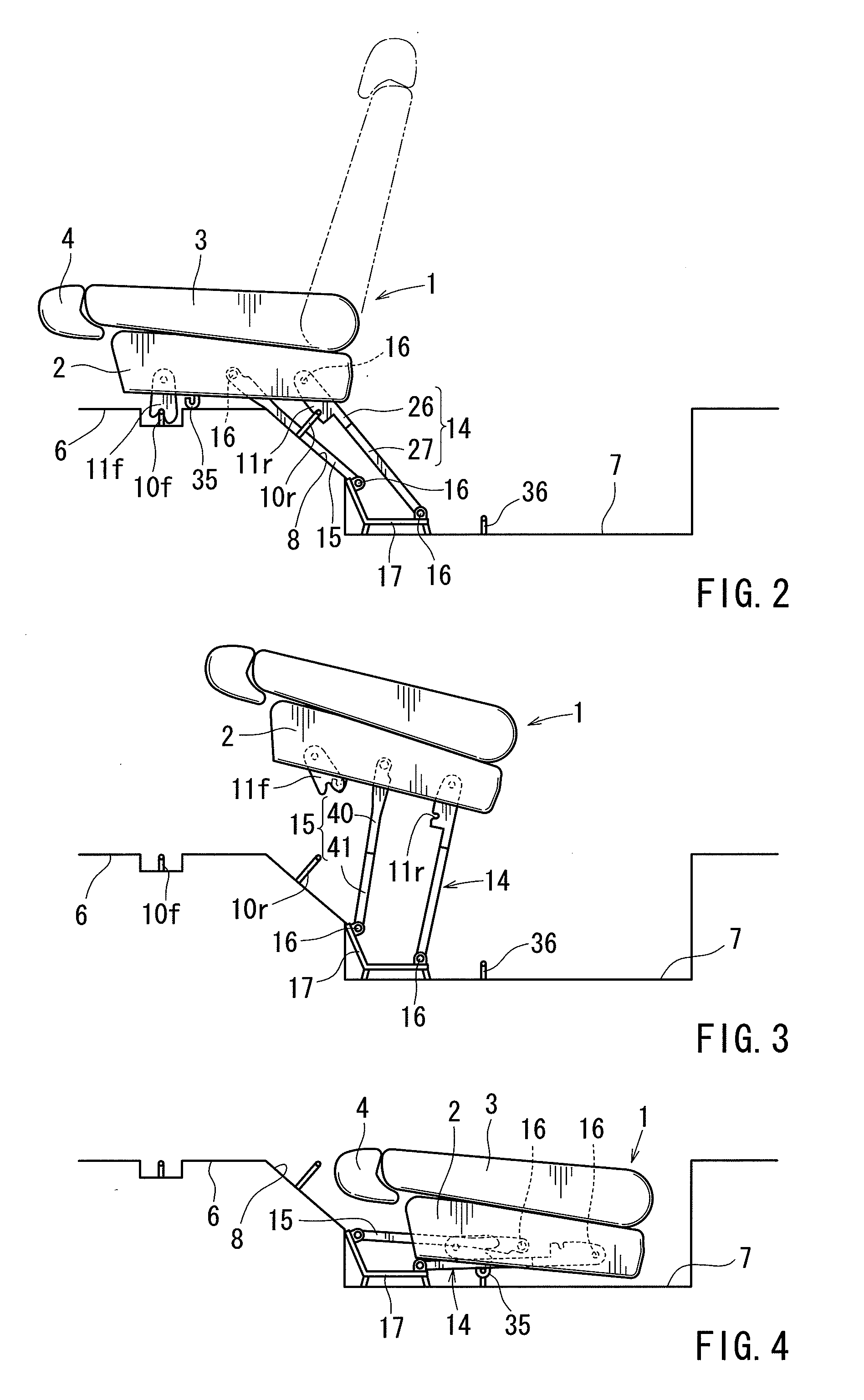
[0023]As is shown in FIG. 2 through FIG. 4, a seat 1 has a seat cushion 2 serving as the seating portion for a passenger, a seat back 3 serving as the back rest, and a head rest 4 to support the head. The seat 1 is applicable as a rear seat for vehicle, such as an automobile. The seat back 3 is coupled to the seat cushion 2 via an unillustrated reclining mechanism. The seat back 3 is pivotally movable in a front-rear direction between an in-use posture uprising on the seat cushion 2 and a not-in-use posture folded forward over the seat cushion 2. The in-use posture of the seat cushion 2 is indicated by a virtual line in FIG. 2. The not-in-use posture of the seat cushion 2 is indicated by a solid line in FIG. 2. The seat 1 is movable in the front-rear direction between the in-use position shown in FIG. 2 and the stored position shown in FIG. 4. The in-use position is a position at which the seat 1 is fixed on a floor 6 for a passenger to be seated thereon. The stored position is a po...


PUM


Abstract

One aspect of the invention includes a seat movable in a front-rear direction between an in-use position and a stored position. The seat is moved in the front-rear direction via a link. The link is coupled pivotally in the front-rear direction. One end of the link is coupled to a coupling member fixed to the seat. The other end of the link is coupled to a coupling member fixed to the floor. The link and the respective coupling members are coupled to each other using an axial member. The insertion hole is formed in a shape that inhibits the axial member from undergoing positional displacement in the front-rear direction within the insertion hole when the seat is at the in-use position and allows the axial member to undergo positional displacement in the front-rear direction within the insertion hole as the seat is moved from the in-use position to the stored position.

Description

BACKGROUND OF THE INVENTION[0001]1. Field of the Invention[0002]The present invention relates to a storable seat for vehicle that is movable in a front-rear direction between an in-use position and a stored position.[0003]2. Description of Related Art[0004]A storable seat disclosed in JP 2004-276816A is configured in such a manner that the seat is movable in a front-rear direction between an in-use position and a stored position via a link mechanism provided between the seat and the floor. The link mechanism is formed of an intermediate link and a rear link. Although a detailed description is omitted in the cited reference, the upper ends of the both links are coupled to the inner frame of the seat. The lower ends of the both links are also coupled to a stopper piece fixed to the floor. The inner frame and the stopper piece serve as coupling members. Both links are coupled to the coupling members without rattling. In other words, the both links will never undergo positional displace...

Claims


Application Information

Patent Timeline
Patent Type & Authority Applications(United States)
IPC IPC(8): B60N2/10
CPCB60N2/3011B60N2/309B60N2/3079B60N2/3065
Inventor MITSUHASHI, ATSUTAKA
Owner TOYOTA BOSHOKU KK
Why Eureka
Try Eureka