

Steering wheel
- Summary
- Abstract
- Description
- Claims
- Application Information
AI Technical Summary
Benefits of technology
Problems solved by technology
Method used
Image

Examples
first embodiment
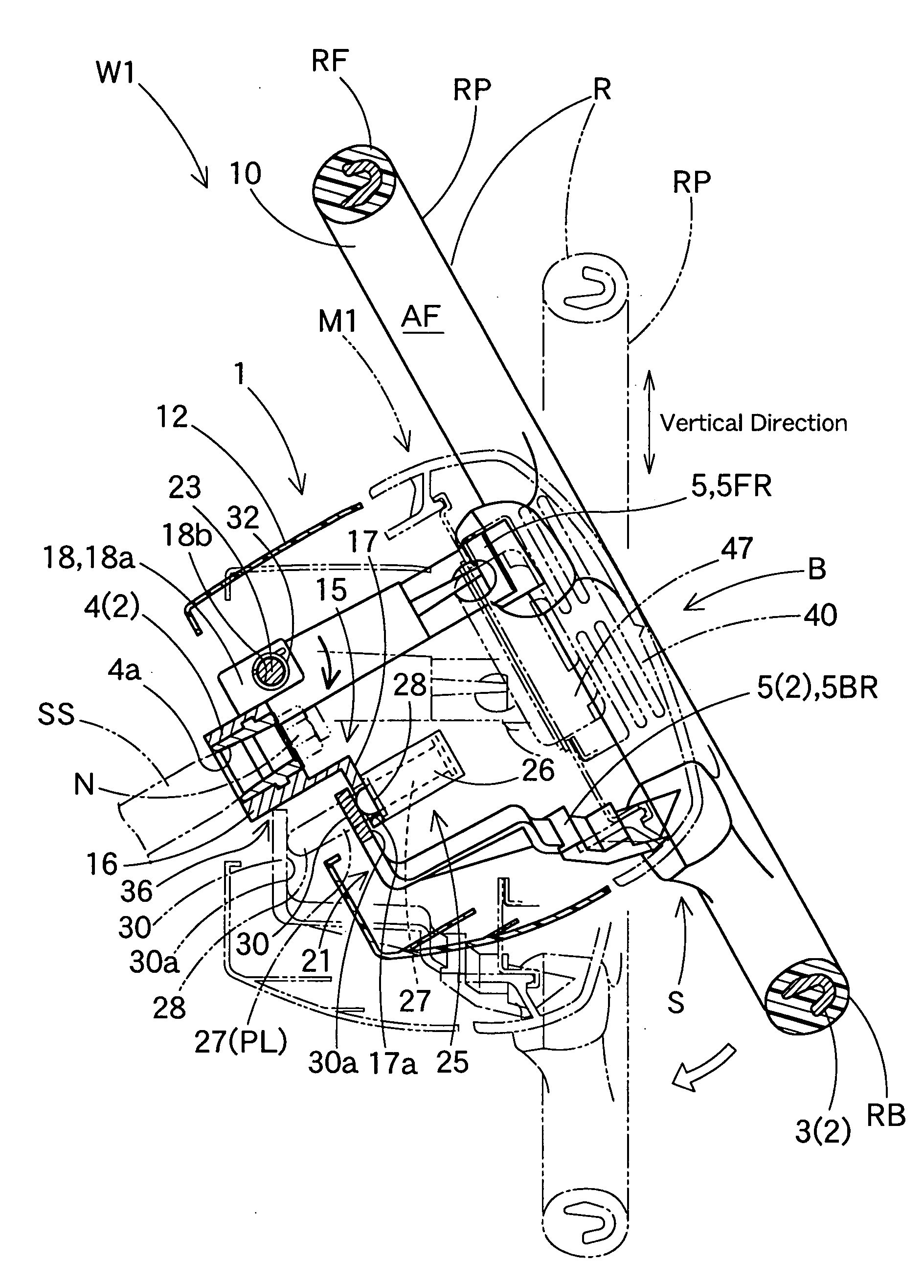
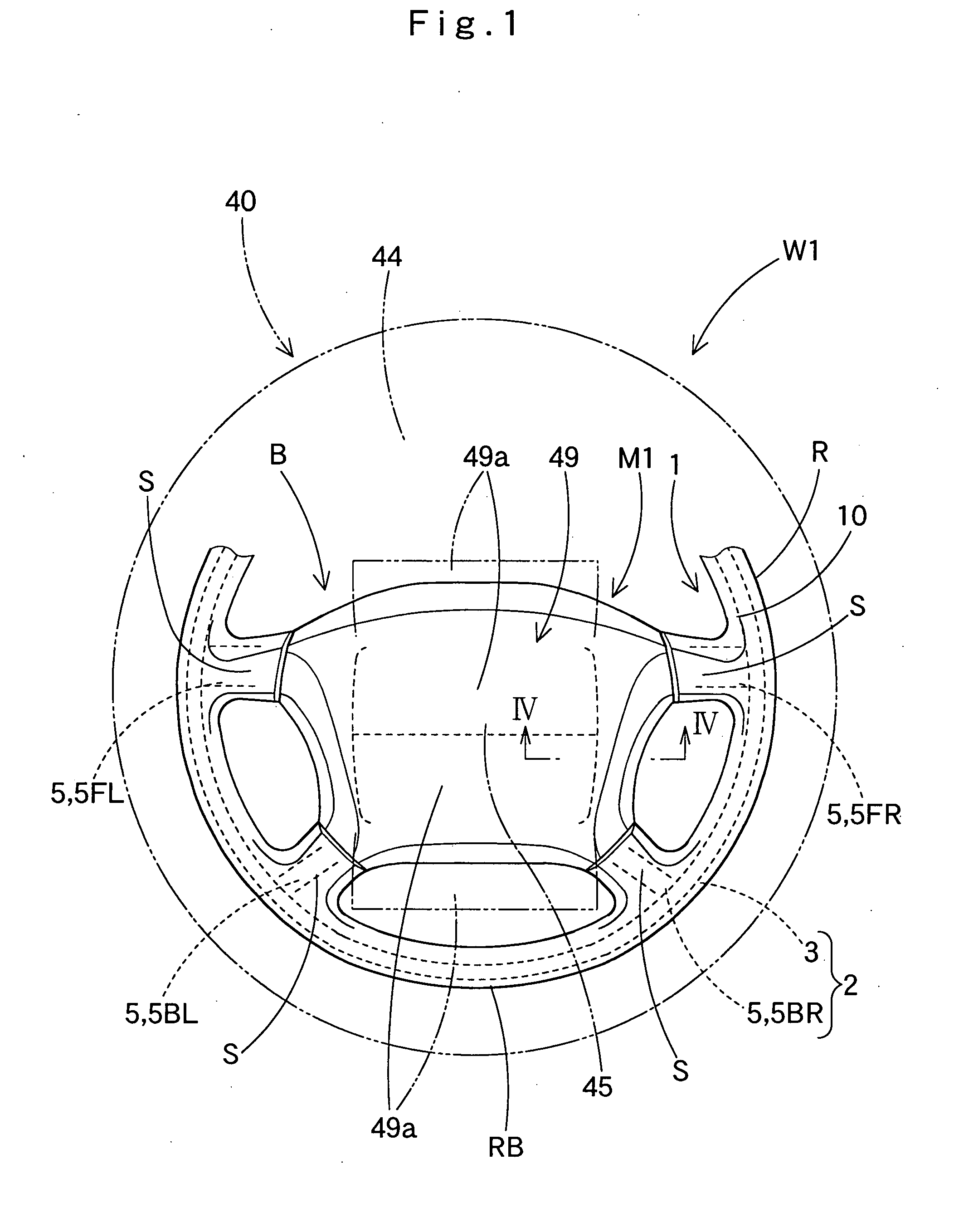
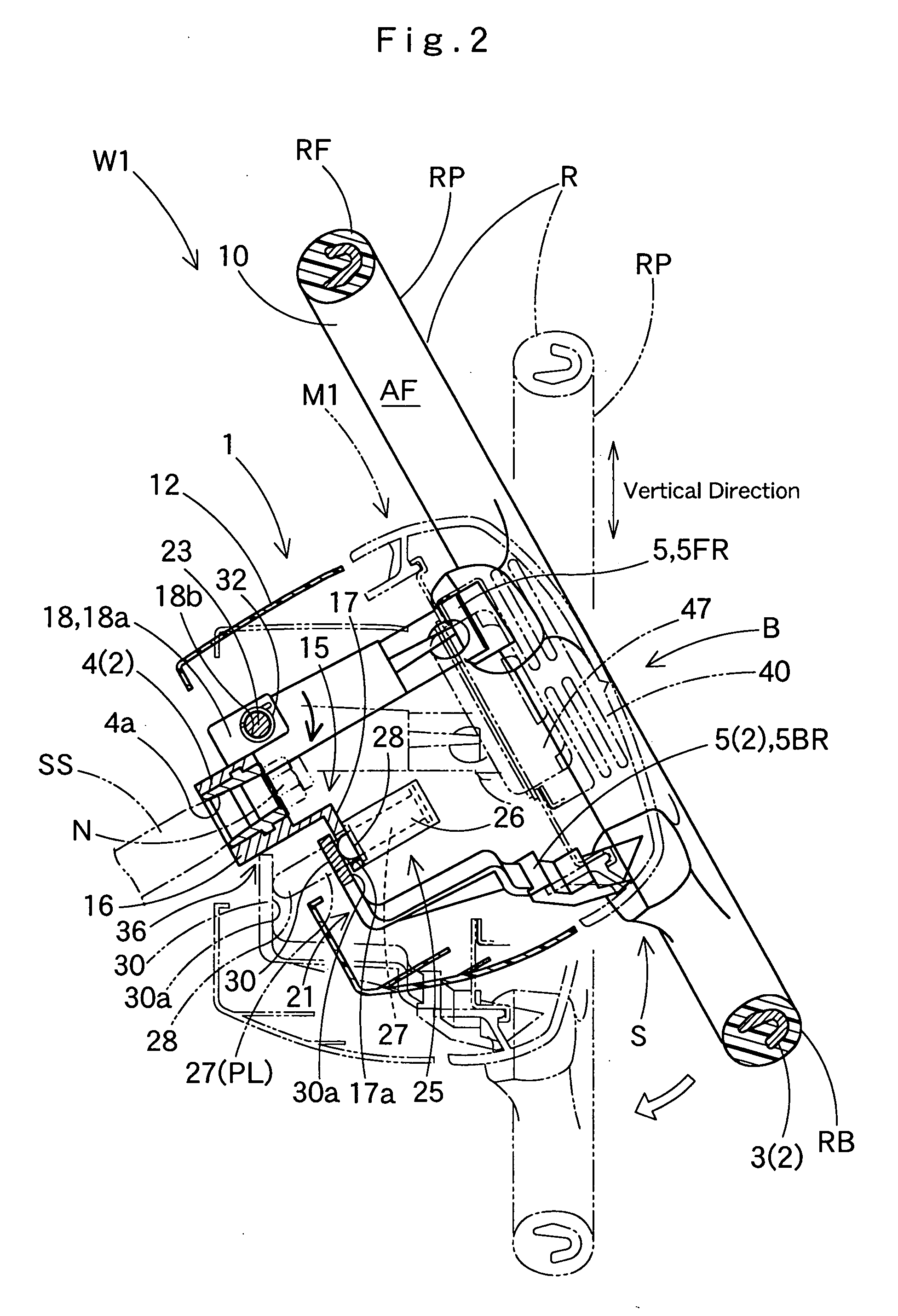
[0091]FIGS. 1 and 2 illustrate a steering wheel W1 according to the present invention. Steering wheel W1 includes a wheel body 1 and an airbag apparatus M1 disposed on top of a boss area B at the center of wheel body 1. Wheel body 1 includes an annular ring R, a boss area B and four spokes S. Ring R is for holding at the time of steering operation. Boss area B is disposed at the center of ring R, and is joined with a steering shaft SS. Spokes S connect ring R and boss area B. Two of the four spokes S are arranged at the left hand side of steering wheel 1 whereas the rest of spokes S are arranged at the right hand side. Underneath wheel body 1 is a lower cover 12 made from synthetic resin for covering the lower side of boss B. Since steering shaft SS diagonally extends downward and forward along the longitudinal direction, a ring plane RP, i.e. a top plane of ring R expands orthogonal to the axial direction of steering shaft SS when wheel body 1 or steering wheel W1 is secured to the...
third embodiment
[0131] In the third embodiment, if control device 60 judges that an impact is unavoidable based on signals fed from pre-crash sensor 62, it activates actuator 26B to launch rod 27B1 which has the longest projected length. If rod 27B1 presses the top face 30a of movable base 30 of ring side division 21, ring side division 21 rotates clockwise about rotary shaft 23 resisting the biasing force of springs 32 such that ring plane RP is aligned along the vertical direction (see solid lines and double-dotted lines in FIGS. 14, 15A and 15B).
[0132] If control device 60 acknowledges that the impact was avoided within a predetermined time period, it retracts rod 27B1 so ring side division 21 returns to the original position.
[0133] On the contrary, if control device 60 detects a collision based on signals fed from crash sensor 61, it activates inflator 47 to inflate airbag 40 (FIG. 15B), so that torso DB of driver D is received by protection plane 45 expanded wide and upright of airbag 40, the...
fourth embodiment
[0142] In operation of steering wheel W4 of the fourth embodiment, when control device 60 detects an impact based on signals from crash sensor 61 while traveling straight ahead, it activates actuator 26C or regulating member 19 to pull rod 27C out of retaining holes 34. Then as shown in FIGS. 18A and 18B, rod 27C stops holding movable base 30C thereby ring side division 21 rotates about rotary shaft 23 by its own weight such that ring plane RP is aligned along the vertical direction. Since movable base 30C abuts against stopper 36, ring plane RP is held in the upright orientation. Control device 60 further activates inflator 47 to inflate airbag 40 (FIG. 18C), so that airbag 40 receives torso DB of driver D by its protection plane 45 expanded wide and upright and absorbs the kinetic energy of driver D.
[0143] Further in the fourth embodiment, if rotation drive mechanism 25C is once activated to pull rod 27C out of retaining holes 34, ring side division 21 is freed from movement contr...
PUM
 Abstract
Description
Claims
Application Information