Centrifugal separator

a centrifuge and separator technology, applied in the direction of centrifuges, rotary centrifuges, etc., can solve the problems of difficult operation of the centrifuge rotor, etc., and achieve the effect of high centrifuge rotor and stable operation

Active Publication Date: 2011-09-01
ALFA LAVAL CORP AB
View PDF18 Cites 12 Cited by
  • Summary
  • Abstract
  • Description
  • Claims
  • Application Information

AI Technical Summary

Benefits of technology

[0006]The present invention resides in one aspect in a centrifugal separator which can be manufactured with a relatively high centrifuge rotor and which ca

Problems solved by technology

Centrifugal separators of a conventional kind also have a limitation with regard to how high the centrifuge rotor and the disk pack

Method used


Image

  • Centrifugal separator
  • Centrifugal separator
  • Centrifugal separator

Examples


Embodiment Construction

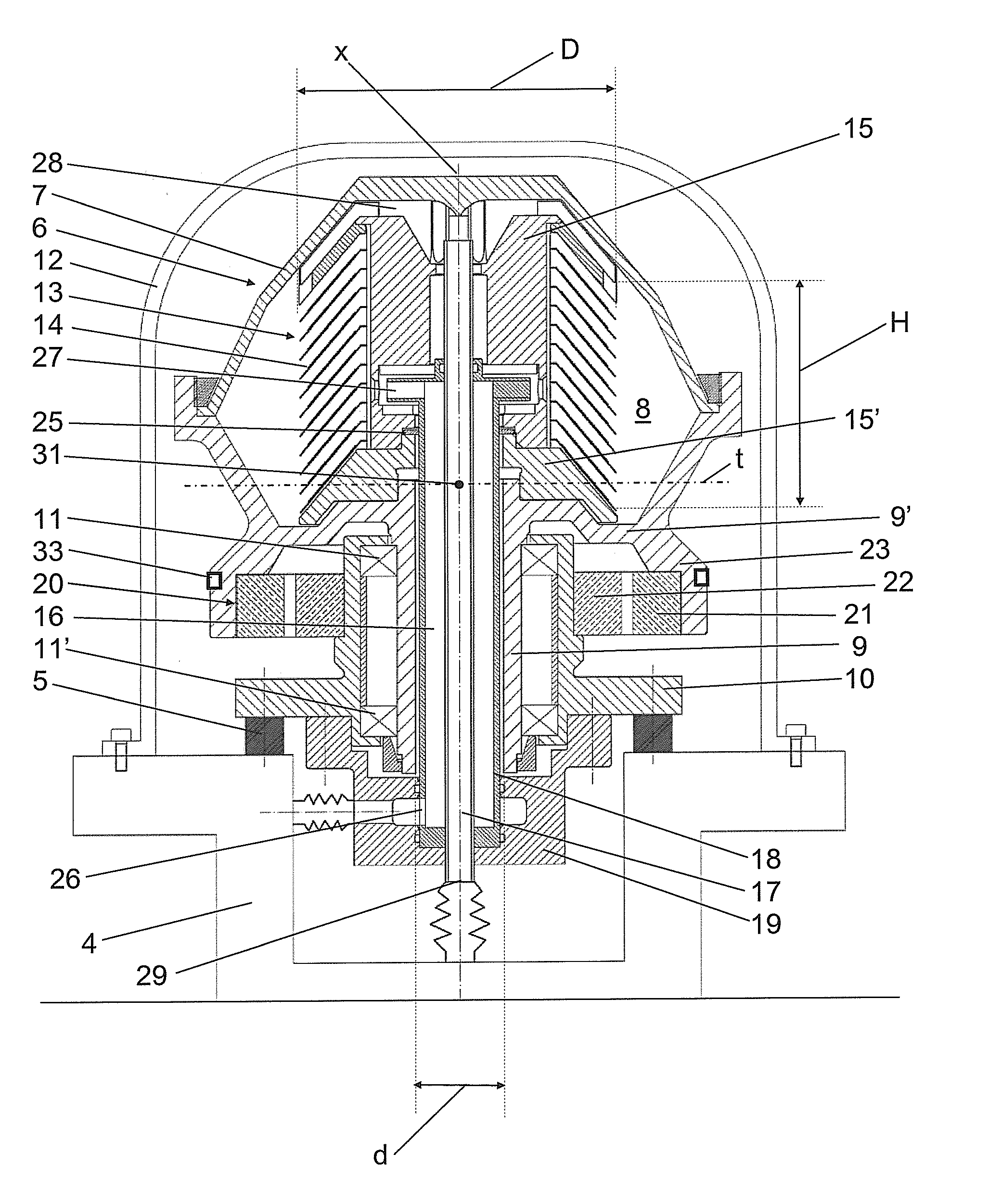
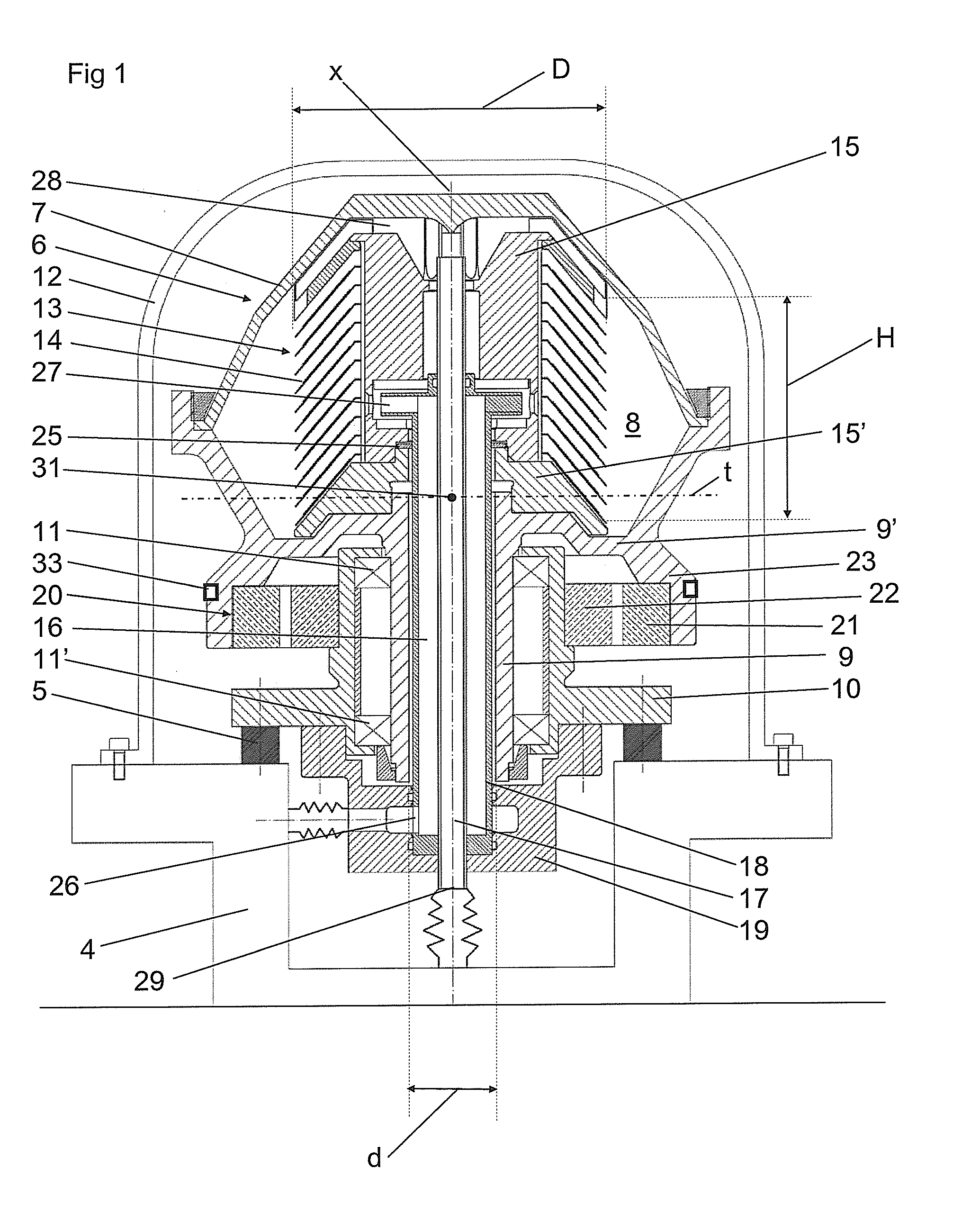
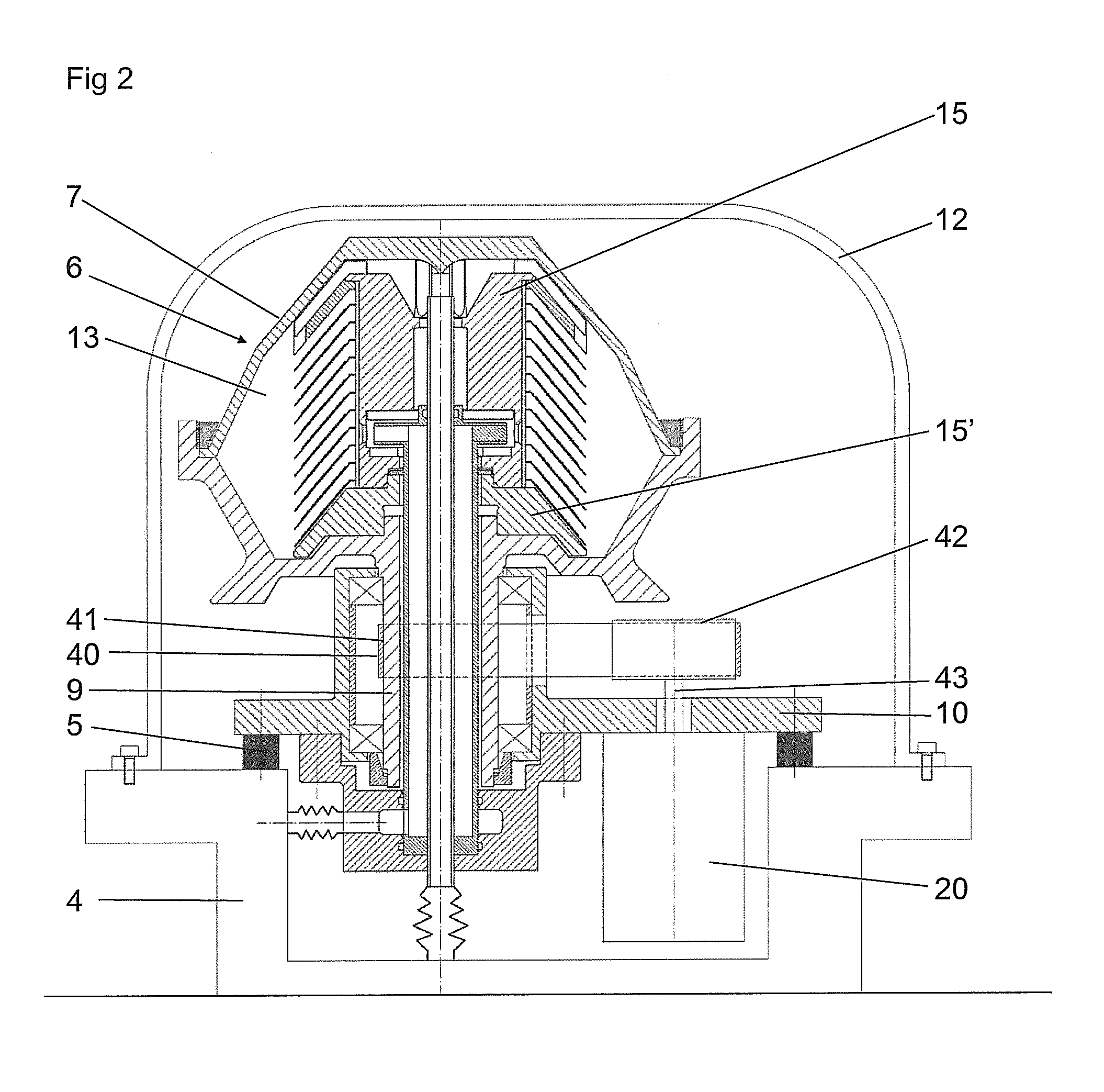
[0022]FIG. 1 discloses a centrifugal separator which comprises or consists of a stationary part, a non-rotating part and a rotating part.

[0023]The stationary part forms a base 4 which is located on a ground, for instance a floor. The non-rotating part is elastically connected to the stationary part, i.e. to the base 4, by means of an elastic connection 5. The elastic connection 5 may comprise a number of elastic elements, which have elastic and dampening properties, or any form of active damping elements. The elastic elements are disposed around the axis x of rotation and, in the embodiments disclosed, in an annular configuration. The rotating part is configured to rotate around an axis x of rotation and comprises a centrifuge rotor 6. The elastic connection 5, i.e. the elastic elements or any other active damping elements, are configured in such a way that the rotating part and the non-rotating part may pivot or oscillate in relation to the stationary part and in such a way that th...


PUM


Abstract

In a centrifugal separator having a stationary part, a non-rotating part, is elastically connected to the stationery part, and a rotating part, rotates around an axis of rotation and comprises a centrifuge rotor and a rotating bearing-receiving element. The centrifuge rotor comprises a disk package with a plurality of separating disks. The rotating part is journalled in the non-rotating part so that the rotating part and the non-rotating part are commonly pivotable relative to the stationary part. A drive arrangement drives the rotating part about the axis of rotation within a range of revolutions. An inlet channel extends into the inner separation space for feeding of a medium to be separated. An outlet channel extends out from the inner separation space for discharge of a separated product. The bearing-receiving element is tubular. At least one of the inlet channel and the outlet channel extends through the bearing-receiving element.

Description

FIELD OF THE INVENTION[0001]The present invention refers to a centrifugal separator.BACKGROUND[0002]A centrifugal separator according to the following description is known and comprises a stationary part forming a base, non-rotating part, which comprises a bracket and which is elastically connected to the stationary part by means of an elastic connection, and a rotating part which is configured to rotate around an axis of rotation and comprises a centrifuge rotor. The centrifuge rotor comprises a rotor casing, which forms an inner separation space, and a rotating bearing-receiving element in the form a spindle. The centrifuge rotor comprises a disk package with a plurality of separating disks. The rotating part is journalled in a stiff manner in the non-rotating part in such a way that the rotating part and the non-rotating part are commonly pivotable in relation to the stationary part by means of the elastic connection. A drive arrangement drives the rotating part to rotate around ...

Claims


Application Information

Patent Timeline
IPC IPC(8): B04B9/02B04B9/00
CPCB04B9/04B04B9/08B04B1/08B04B11/02B04B9/12B04B1/04B04B7/12
Inventor KLINTENSTEDT, KJELL
Owner ALFA LAVAL CORP AB
Why Eureka
Try Eureka