
Exposure apparatus and method of manufacturing device
a technology of exposure apparatus and manufacturing device, which is applied in the field of exposure apparatus and a manufacturing device, can solve the problems of generating pattern overlay errors, reducing the throughput of the method, and not using the plurality of reticles to perform successive exposure operations
- Summary
- Abstract
- Description
- Claims
- Application Information
AI Technical Summary
Benefits of technology
Problems solved by technology
Method used
Image

Examples
first embodiment
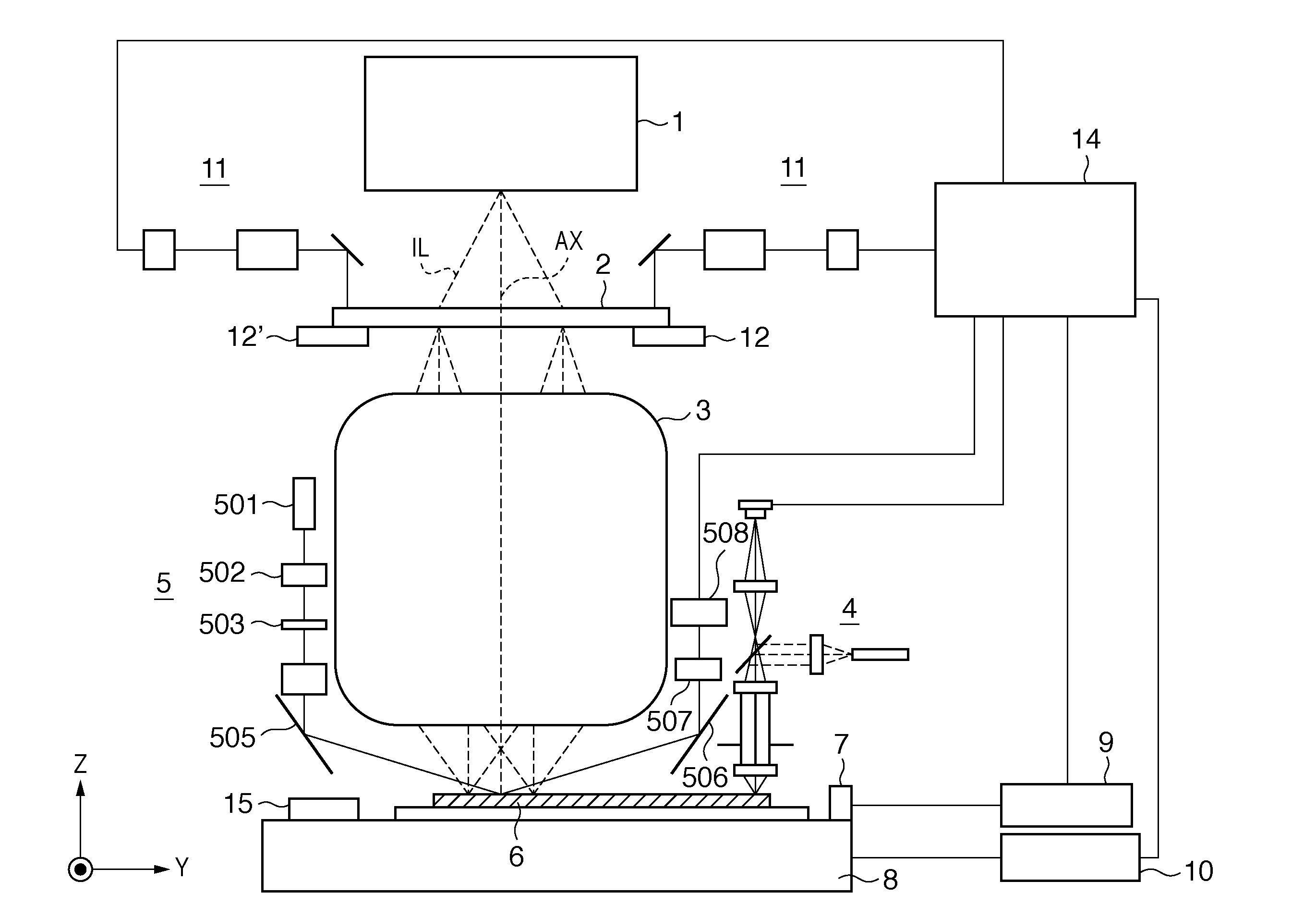
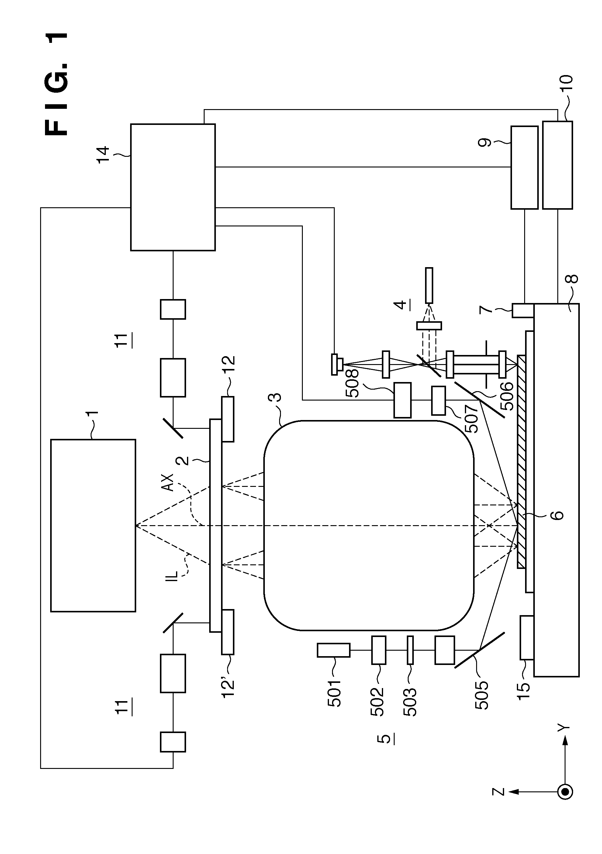
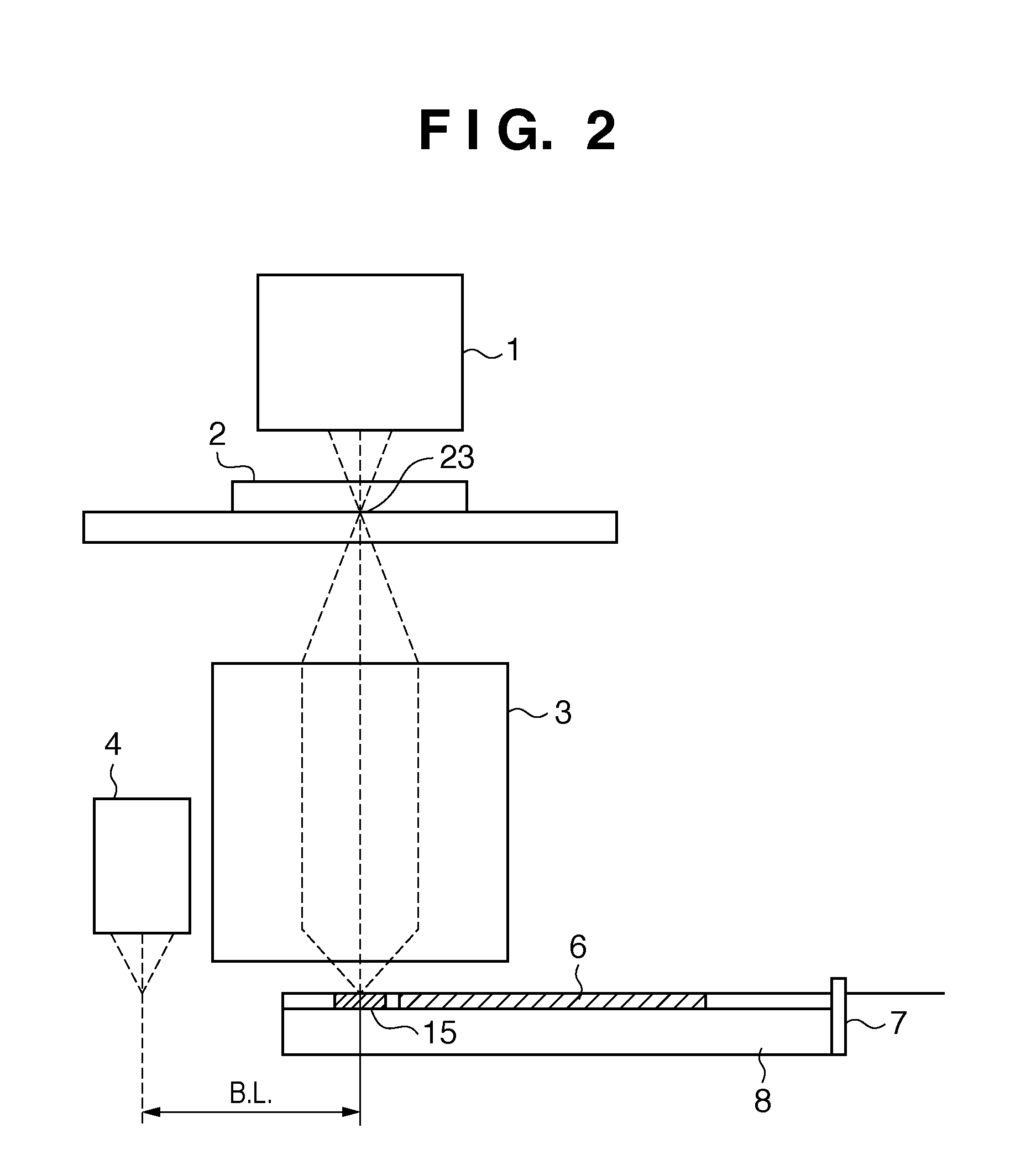
[0028]An exposure apparatus will be schematically explained with reference to FIG. 1. The exposure apparatus transfers the pattern of a reticle 2 onto a substrate 6 via a projection optical system 3. Light emitted by an illumination system 1 which performs illumination with exposure light illuminates the reticle 2 arranged with reference to reticle set marks 12 and 12′ formed on a reticle stage (not shown). The reticle 2 is positioned by a reticle alignment scope 11 which can be used to simultaneously observe the reticle set marks 12 and 12′ and reticle set marks (not shown) formed on the reticle 2. The alignment scope 11 uses the exposure light source as an observation light source, can move above the reticle 2, and can be used to observe both the surfaces of the reticle 2 and substrate 6 through the reticle 2 and the projection optical system 3 at a plurality of image heights in the projection optical system 3. In other words, the alignment scope 11 can also detect positions above...
second embodiment
[0057]A method of estimating and correcting reticle contraction in a standby state has been described in the first embodiment. However, a method of correcting that contraction with higher accuracy will be explained with reference to FIGS. 6A and 6B in the second embodiment. Note that the same reference numerals as in the first embodiment denote elements having the same functions in the second embodiment, and a detailed description thereof will not be given. FIG. 6A is a side view of the reticle vicinity when viewed sideways, and FIG. 6B is a top view of the reticle vicinity when viewed from above. The feature in FIGS. 6A and 6B is that a position detector 32 or 32′ which can be used to observe and measure alignment marks formed on a reticle 2 is set at the standby position of the reticle 2. The position detector 32 or 32′ is a second detector which detects the contraction state of the reticle 2 in a standby state, and measures the shape of a given reticle 2 at the standby position a...
third embodiment
[0060]A method of detecting alignment marks formed on a reticle 2 to detect the shape of the reticle 2 during standby, and performing exposure based on the detected information has been described in the second embodiment. Another embodiment will be explained with reference to FIGS. 8 and 9 herein.
[0061]In this embodiment, an infrared camera 42 is provided so as to measure the temperature distribution of a reticle 2. The infrared camera 42 captures infrared rays coming from the entire surface or a specific region of the reticle 2, and measures the temperature distribution of the reticle 2 from the captured infrared rays. The shape of the reticle 2 in a standby state is predicted based on the measured temperature distribution. The infrared camera 42 is a fourth detector which detects the temperature distribution of the reticle 2 in a standby state.
[0062]The shape based on the temperature distribution may be measured in advance, or the relationship between the temperature distribution ...
PUM
 Abstract
Description
Claims
Application Information