Ferrite magnet device, nonreciprocal circuit device, and composite electronic component

a non-reciprocal circuit, ferrite magnet technology, applied in the direction of magnetic materials, magnetic bodies, electrical devices, etc., can solve the problems of variation in the degree of shrinkage, inability to solve the problem of precision limitation, and variability in characteristics, so as to prevent manufacturing errors caused by sintering

Active Publication Date: 2009-12-24
MURATA MFG CO LTD
View PDF4 Cites 5 Cited by
  • Summary
  • Abstract
  • Description
  • Claims
  • Application Information

AI Technical Summary

Benefits of technology

[0008]To overcome the problems described above, preferred embodiments of the present invention provide a ferrite magnet device, a nonreciprocal circuit device, and a composite electronic component that can prevent manufacturing errors caused by sintering.
[0013]According to preferred embodiments of the present invention, the process for manufacturing a ferrite magnet device does not requires a sintering step. Therefore, the degradation of precision due to a shrinkage error is prevented.

Problems solved by technology

The nonreciprocal circuit devices described in Japanese Unexamined Patent Application Publication No. 2002-299912 and Japanese Patent No. 3649162 require complex assemblies, which cause variations in characteristics due to deviations in the assembly, since the permanent magnet and ferrite element having central electrodes are not combined.
The nonreciprocal circuit device described in Japanese Patent No. 3649162, in particular, has a problem in which the central electrodes that are made of a photosensitive conductor paste undergo shrinkage after sintering, and thus, the precision is limited due to variation in the degree of shrinkage.
However, the problem of variation in the degree of shrinkage has not been solved since the central electrodes require sintering.

Method used


Image

  • Ferrite magnet device, nonreciprocal circuit device, and composite electronic component
  • Ferrite magnet device, nonreciprocal circuit device, and composite electronic component
  • Ferrite magnet device, nonreciprocal circuit device, and composite electronic component

Examples


first preferred embodiment

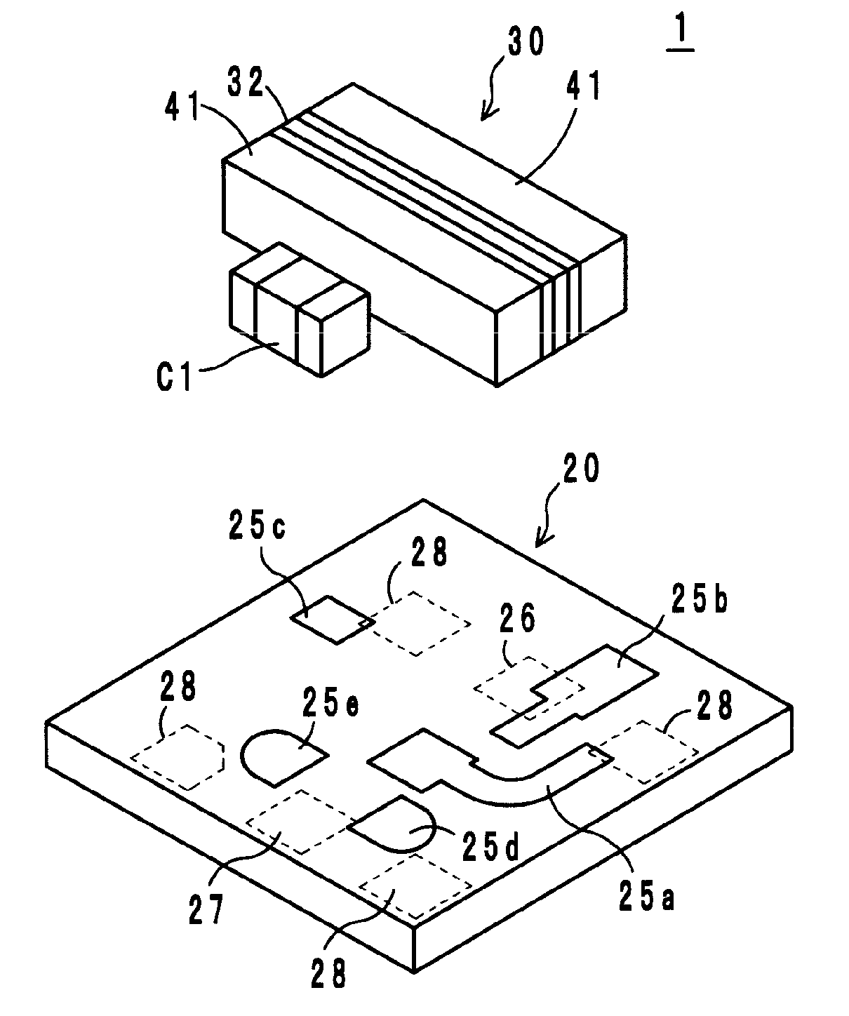
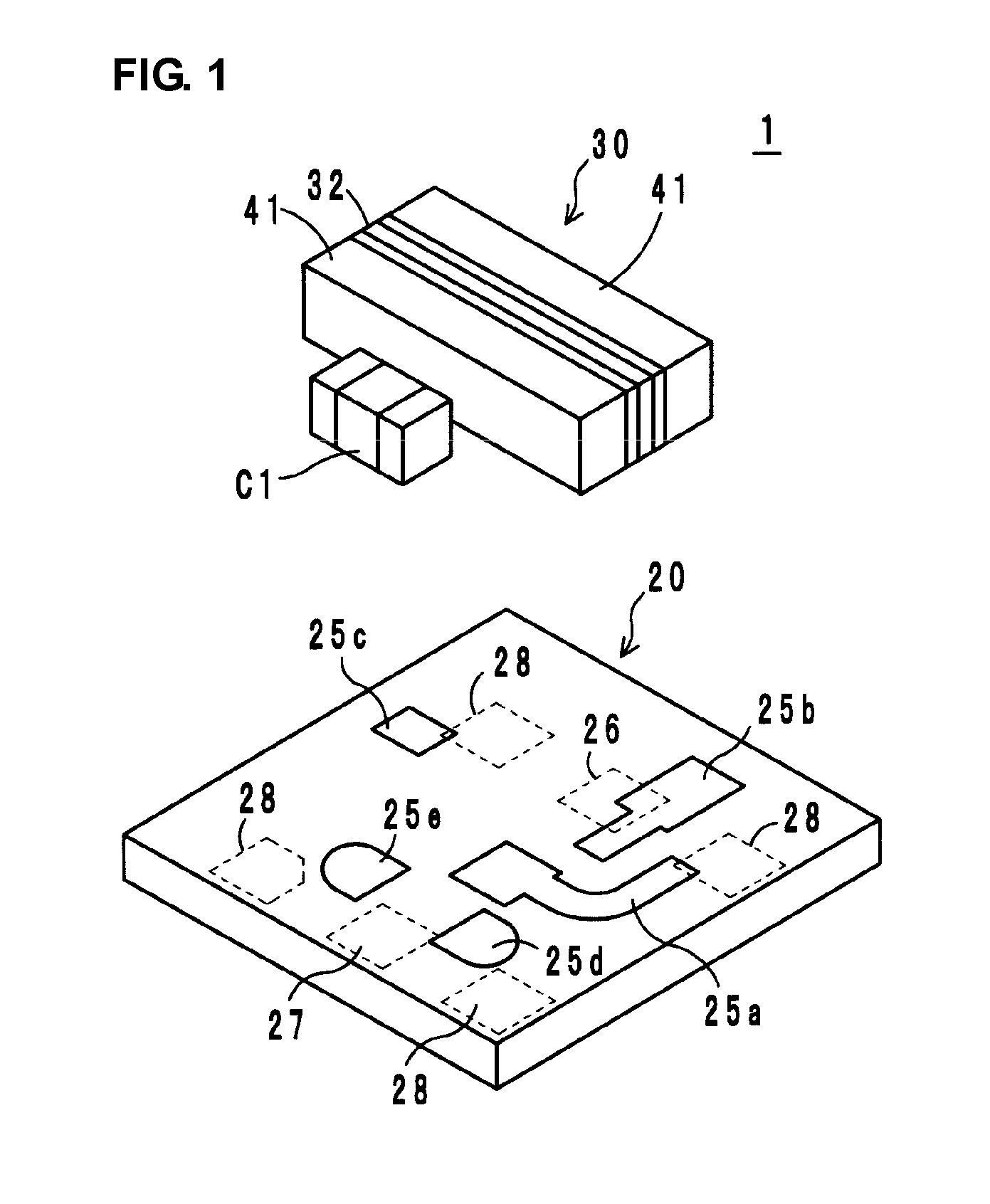
[0030]A first preferred embodiment of the present invention will be described with reference to FIGS. 1 to 5. FIG. 1 shows an exploded perspective view of a 2-port isolator 1 according to the first preferred embodiment. The 2-port isolator 1 is a lumped-parameter isolator, and includes a circuit substrate 20, a ferrite magnet device 30 having a ferrite element 32 and a pair of permanent magnets 41, and matching circuit devices, for example, a capacitor C1 is mounted on the circuit substrate 20, and other devices are provided in the circuit substrate 20.

[0031]Referring to FIG. 2, the ferrite element 32 includes a first central electrode 35 and a second central electrode 36 electrically isolated from one another and arranged on a front main surface 32a and a back main surface 32b thereof. Here, the ferrite element 32 has a substantially rectangular parallelepiped shape in which the main surface 32a and the opposite back main surface 32b arranged substantially in parallel.

[0032]The per...

second preferred embodiment

[0053]A second preferred embodiment of the present invention will be described with reference to FIG. 10. FIG. 10 shows an exploded perspective view of a 2-port isolator 2 according to the second preferred embodiment. The 2-port isolator 2 has substantially the same structure as the first preferred embodiment except that all of the matching circuit devices C1, C2, CS1, CS2, and R are chip devices and are soldered to the surface of a printed circuit board 20A. In addition to the terminal electrodes 25a, 25b, and 25c arranged to connect both ends of the first and second central electrodes 35 and 36, the terminal electrodes 25d and 25e arranged to be connected to corresponding matching circuit devices are preferably provided on the surface of the printed circuit board 20A. Input and output electrodes and a ground electrode are also provided, although not shown.

third preferred embodiment

[0054]A third preferred embodiment of the present invention will be described with reference to FIGS. 11 and 12. FIG. 11 shows a composite electronic component 3 according to the third preferred embodiment. The composite electronic component 3 is a module configured by mounting the 2-port isolator 2 and a power amplifier 81 on the surface of a printed circuit board 82. Necessary chip circuit devices 83a to 83f are also mounted around the power amplifier 81.

[0055]FIG. 12 shows a circuit configuration of the composite electronic component 3. The output of an impedance matching circuit 86 is input to the high-frequency power amplifier 81, whose output is input to the 2-port isolator 2 via an impedance matching circuit 85.


PUM

PropertyMeasurementUnit
temperatureaaaaaaaaaa
magnetic fieldaaaaaaaaaa
photosensitiveaaaaaaaaaa

Abstract

A ferrite magnet device, a nonreciprocal circuit device, and a composite electronic component are provided. The ferrite magnet device includes a ferrite element having a plurality of central electrodes arranged to intersect one another in an electrically insulated state, and a pair of permanent magnets fixed to both main surfaces of the ferrite element so as to apply a direct current magnetic field to the ferrite element. The central electrodes are made of metal foils provided on both main surfaces of the ferrite element, with adhesive layers therebetween. Electrodes provided on the upper and lower surfaces of the ferrite element are formed by plating in through holes.

Description

BACKGROUND OF THE INVENTION[0001]1. Field of the Invention[0002]The present invention relates to a ferrite magnet device, a nonreciprocal circuit device including the ferrite magnet device, and a composite electronic component including the nonreciprocal circuit device. The nonreciprocal circuit device may be an isolator or a circulator, for example, used in a microwave band.[0003]2. Description of the Related Art[0004]Typical nonreciprocal circuit devices, such as isolators or circulators, have a characteristic in which a signal is transmitted in a predetermined specific direction and not transmitted in the reverse direction. To utilize this characteristic, an isolator, for example, is used in the transmitter circuit unit of a mobile communication apparatus such as a vehicle telephone or a cellular phone.[0005]Usually, such a nonreciprocal circuit device includes a ferrite magnet device including a ferrite element having central electrodes provided thereon and a permanent magnet ar...

Claims


Application Information

Patent Timeline
Patent Type & Authority Applications(United States)
IPC IPC(8): H01F1/00
CPCH01P1/36
Inventor WADA, TAKAYAKONISHI, ATSUSHI
Owner MURATA MFG CO LTD
Why Eureka
Try Eureka