Unlock instant, AI-driven research and patent intelligence for your innovation.

Surface Mounting System

Inactive Publication Date: 2010-01-21
PEERLESS INDS
View PDF35 Cites 5 Cited by
  • Summary
  • Abstract
  • Description
  • Claims
  • Application Information

AI Technical Summary

Benefits of technology

[0007]Various embodiments provide for an improved mounting system used to mount an audio / visual device, such as a flat panel display, to a desktop or other substantially horizontal mounting surface. According to various embodiments, a surface mounting system comprises a support assembly which mates with one or more collars that are positioned above and below the surface to which the mounting system is secured. The collars secure the rest of the mounting system to the desktop, and the collars may also secure other components which serve to prevent the support assembly from rotating in an undesirable manner. With this arrangement, only a single hole needs to be made in the desktop or other surface to which the system is mounted, while the number of components that are needed to attach the mounting system to the surface in a secure manner can be minimized. No locking agent is needed to properly and sufficiently secure the surface mounting system to the desktop.

Problems solved by technology

Although there are a number of desktop mounting systems conventionally available, many of these mounts literally rest on top of the desk or other surface, meaning that it is not difficult for the mount (and therefore the display) to be accidentally bumped and thereby damaged.
Additionally, this type of desktop mount is often not capable of supporting displays which are relatively large in size.
Although such arrangements help to prevent the mount and display from falling over and being damaged, these mounting systems also require that the user physically damage the desktop or other surface by drilling a plurality of holes into it.

Method used


Image

  • Surface Mounting System
  • Surface Mounting System
  • Surface Mounting System

Examples


Embodiment Construction

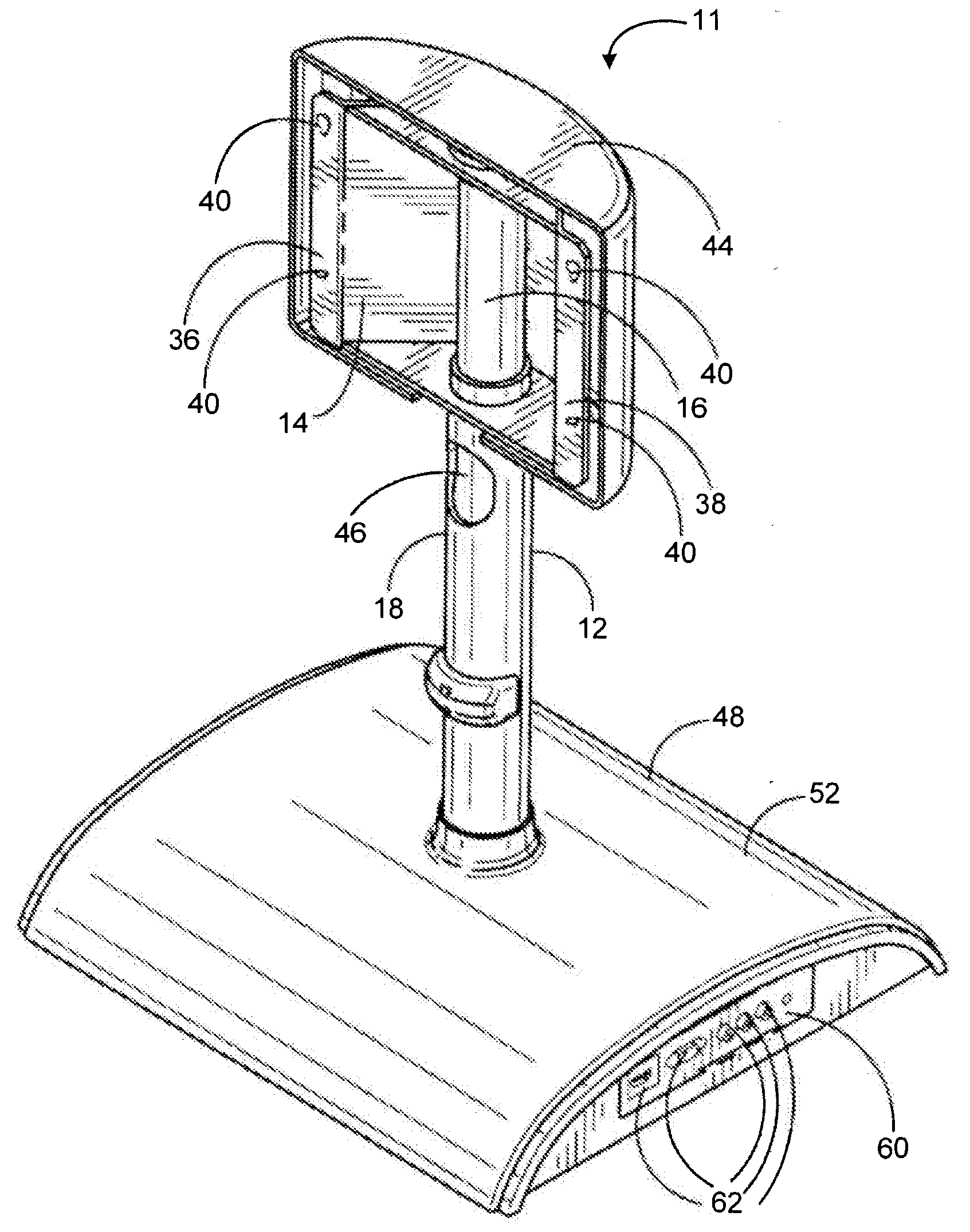
[0020]FIGS. 1-9 depict a surface mounting system 11 constructed according to various embodiments. The surface mounting system 11 comprises a support assembly 12 operatively connected to a device bracket 14. As best shown in FIGS. 8 and 9, the support assembly 12 may comprise an upper support member 16 and an lower support member 18. The upper support member is connected to the device bracket 14 and is operatively connected to the lower support member, which is secured to a desktop 100 or other surface. In one particular embodiment, the upper support member 16 is welded or otherwise securely fastened to the lower support member 18.

[0021]As best shown in FIGS. 8 and 9, an upper device collar 20 and a lower device collar 22 are used to connect the upper support member 16 to the device bracket 14. The device bracket 14 includes an upper device opening 24 and a lower device opening 26, both of which are sized to accept the upper support member 16. The upper device opening 24 also accepts...


PUM


Abstract

An improved mounting system used to mount an audio / visual device, such as a flat panel display, to a desktop or other substantially horizontal mounting surface. According to various embodiments, a surface mounting system comprises a support assembly which mates with one or more collars positioned above and below the surface to which the mounting system is secured. The collars secure the rest of the mounting system to the desktop, and the collars may also secure other components which serve to prevent the support assembly from rotating in an undesirable manner. Only a single hole needs to be made in the desktop or other surface to which the system is mounted, while the number of components that are needed to attach the mounting system to the surface in a secure manner can be minimized. No locking agent is also need to properly and sufficiently secure the surface mounting system to the desktop.

Description

CROSS REFERENCE TO RELATED PATENT APPLICATIONS[0001]The present application claims priority to U.S. Provisional Patent Application No. 61 / 081,819, filed Jul. 18, 2008, and the contents of which are incorporated herein by reference in their entirety.FIELD OF THE INVENTION[0002]The present invention relates generally to mounting systems. More particularly, the present invention relates to mounting systems for audio / visual equipment such as flat panel displays.BACKGROUND OF THE INVENTION[0003]This section is intended to provide a background or context to the invention that is recited in the claims. The description herein may include concepts that could be pursued, but are not necessarily ones that have been previously conceived or pursued. Therefore, unless otherwise indicated herein, what is described in this section is not prior art to the description and claims in this application and is not admitted to be prior art by inclusion in this section.[0004]In recent years, flat panel tele...

Claims


Application Information

Patent Timeline
IPC IPC(8): A47B96/06
CPCF16M11/28F16M11/08Y10S248/917
Inventor GILLESPIE, JOHN MICHAEL
Owner PEERLESS INDS
Features
  • R&D
  • Intellectual Property
  • Life Sciences
  • Materials
  • Tech Scout
  • Unparalleled Data Quality
  • Higher Quality Content
  • 60% Fewer Hallucinations
Learn More