Exposure Device and Method for Producing the Same

a technology of exposure device and lens array, which is applied in the direction of power drive mechanism, printing machine, instruments, etc., can solve the problems of large exposure head, high production cost, and difficulty in fixing (firmly fixing) the light-emitting element to the casing, so as to reduce the cost of producing the image-forming apparatus, and facilitate the cleaning of the lens array

Active Publication Date: 2010-01-28
BROTHER KOGYO KK
View PDF33 Cites 22 Cited by
  • Summary
  • Abstract
  • Description
  • Claims
  • Application Information

AI Technical Summary

Benefits of technology

[0026]In this case, the projection portion is provided on one of the exposure head and the support frame at a portion between the two adjusting members, the projection portion projecting from one of the exposure head and the support frame toward the other of the exposure head and the support frame. Accordingly, even when any excessive force is applied to the exposure head and the exposure head attempts to warp with the two adjusting members as the warpage points, the projection portion and the support frame (or the exposure head) abut or come into contact with each other. Thus, it is possible to suppress the elastic deformation of the exposure head.
[0027]According to the exposure device of the present invention, it is possible to expose the photoconductive body, etc. correctly since the light-emitting sections and the reference portion are in a correct positional relationship. Further, the correct positional relationship between the light-emitting sections and the reference portion makes it possible to complete the production of the image-forming apparatus, etc. only by assembling the exposure device into other member or components of the image-forming apparatus, thereby making it possible to omit any additional step which would be otherwise required for positioning and thus to lower the cost for producing the image-forming apparatus.
[0028]Since the covers which are made of resin and each of which has the height flush with or higher than the light-exit surface of the lens array are arranged on the lens array on both ends, respectively, of the lens array, it is possible to easily perform the cleaning of the lens array and to maintain the image quality satisfactorily.
[0029]According to the present invention, the projection portion is provided on one of the exposure head and the support frame, the projection portion projecting from one of the exposure head and the support frame toward the other of the exposure head and the support frame. Accordingly, it is possible to suppress, with the projection portion, the elastic deformation of the exposure device and to improve the image quality.

Problems solved by technology

When the LED head is produced with such material and such producing method, then there is a problem such that the LED head becomes large-sized and the production cost becomes higher.
Moreover, even if a positioning portion with the concave-convex positioning structure is formed in the casing, it is not easy to fix (firmly fix) the light-emitting element to the casing and while maintaining a positional relationship between the light-emitting section of the light-emitting element and the positioning portion with high precision.
Therefore, the positional relationship between the light-emitting section of the light-emitting element and the concave-convex positioning structure in the conventional apparatus has unsatisfactory or low precision, and there is a problem such that the positioning precision between the photoconductive body and the light-emitting section is low when the casing provided with the concave-convex positioning structure is simply assembled into other member or component.
Further, since the above-described LED head is used in the vicinity of or closely to the photoconductive drum, there is a fear that when the image-forming apparatus such as a printer is used for a long period of time, toner scattered from the photoconductive drum, etc. and / or paper powder generated from a paper sheet, etc. are attached or adhered to the lower surface of the lens array, which in turn lower the image quality.
However, when the corner portions on the both ends of the lens array are pointed or sharp, the cloth, etc. is caught or hooked by the corner portion(s), which in turn makes the cleaning operation with the cloth, etc. complicated.
Moreover, when the cloth caught at the corner portion is torn and the fiber generated from the torn portion of the cloth is adhered to the lower surface of the lens array, there is a fear that the image quality is further lowered.
In addition, in the conventional technique (apparatus), the size of the eccentric cam and / or the spacer needs to be very small since the optical axis-direction distance is short, giving rise to the limitation to the precision in adjustment by the eccentric cam and the cam stroke.
If such limitation is generated, it is not possible to set the optical axis-direction distance highly precisely, giving rise to a possibility that the image quality is lowered.
However, with the above-described structure, when an excessive force is applied to the LED head upon, for example, cleaning the LED head, the LED warps with the cam as the warpage point and is elastically deformed in some cases.
If the LED head is elastically deformed in such a manner, then the direction of the light emitted from the LED head is deviated from the normal direction, thus leading to a problem such that the image quality is lowered.

Method used


Image

  • Exposure Device and Method for Producing the Same
  • Exposure Device and Method for Producing the Same
  • Exposure Device and Method for Producing the Same

Examples


first embodiment

[0044]In the following, a detailed explanation will be given about a first embodiment of the present invention, while appropriately referring to the drawings.

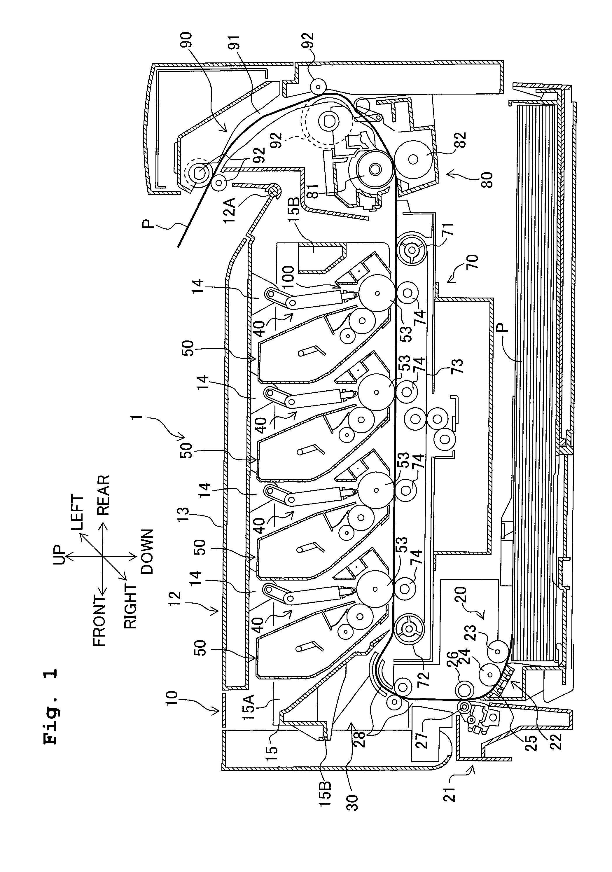
[0045]The following explanation will be given with the directions with a user when using the color printer as the reference. Namely, in FIG. 1, the left side on the sheet surface is “front side”; the right side on the sheet surface is “rear side”; the far side on the sheet surface is “left side”; and the front side on the sheet surface is “right side”. Further, the up and down direction in the sheet surface is “up and down direction”.

[0046]As shown in FIG. 1, a color printer 1 adopting the exposure device of the present invention is provided with, in a housing 10 of the body of the color printer (body housing 10), a paper feeding section 20 which feeds a sheet of paper P (paper sheet P; paper P), an image forming section 30 which forms an image on the paper P fed from the paper feeding section 20, and a paper discharging sectio...

second embodiment

[0094]In the following, a detailed explanation will be given about a second embodiment of the present invention, while appropriately referring to the drawings. Note that in the following explanation, the overall construction of the color printer is same or similar to that of the image forming apparatus provided with the exposure device according to the first embodiment, same reference numerals are assigned to parts or components same as those of the first embodiment, and any explanation therefor will be omitted. The characteristic part(s) of the second embodiment of the present invention will be explained in detail as below.

Construction of the LED Unit

[0095]A detailed explanation will be given about an LED unit 340 as the characteristic part of the present invention.

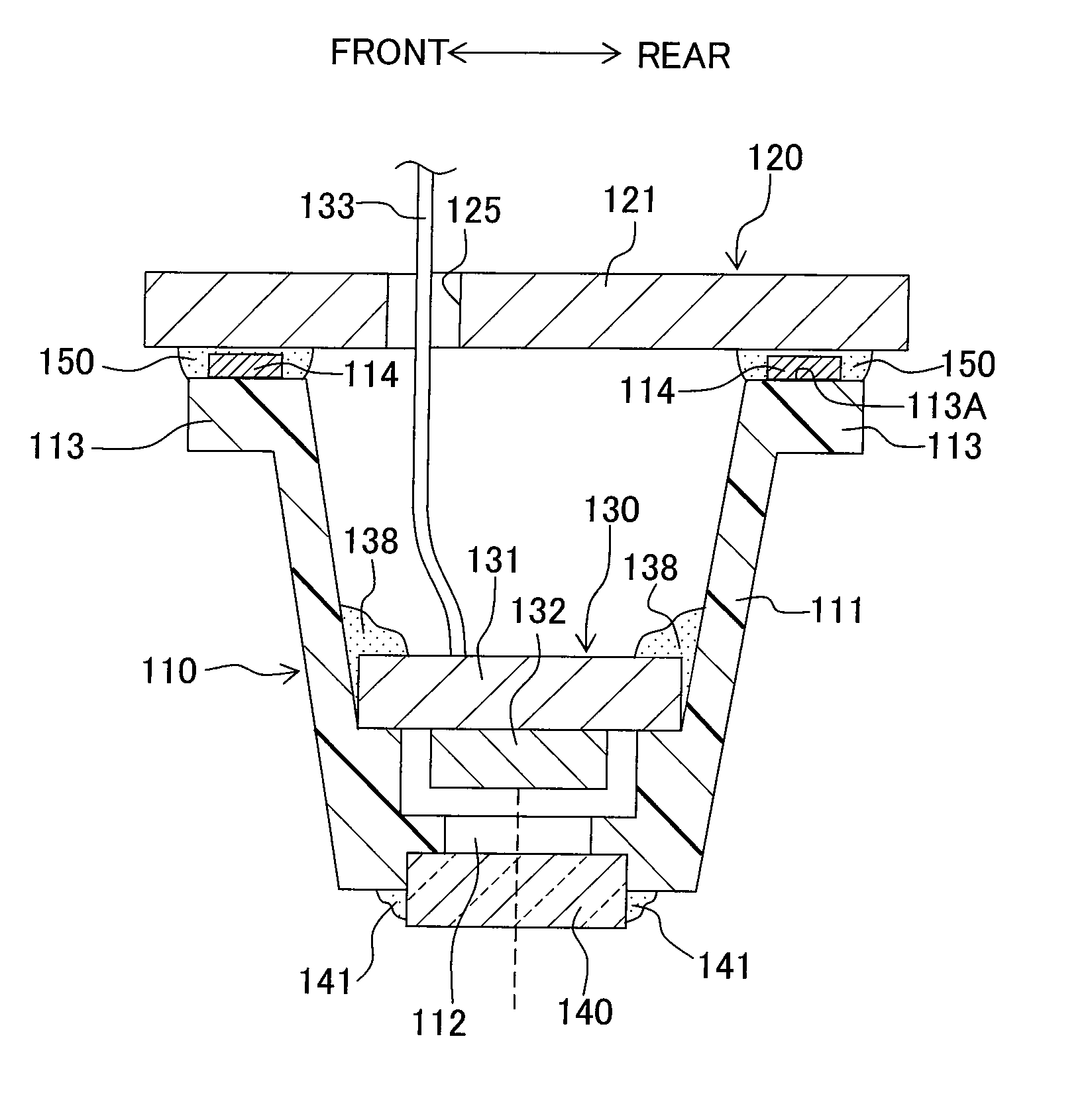
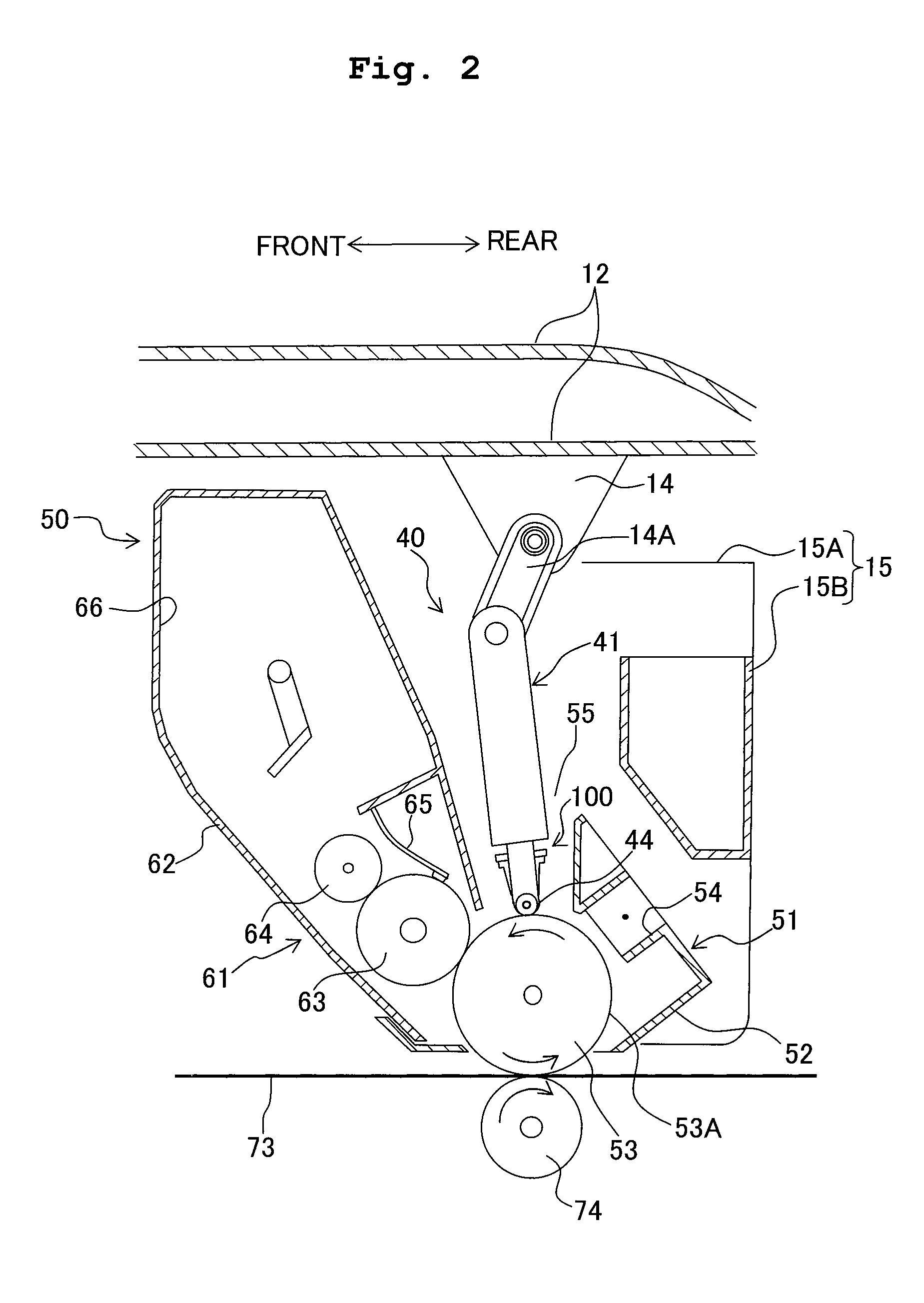
[0096]As shown in FIGS. 8 and 9, the LED unit 340 mainly includes an elongated LED head 341 as an example of the exposure member; a support frame 343 made of resin; two guide rollers 344 as an example of the distance-mai...


PUM


Abstract

There is provided an exposure device including an exposure head having a light-emitting member which has a plurality of light-emitting sections arranged in a row and a casing which holds the light-emitting member and which is elongated in a longitudinal direction orthogonal to an optical axis direction of a light emitted from the light-emitting sections; and an elongated frame member fixed to the casing and having a reference portion at which the frame member is positioned with respect to the light-emitting sections; wherein the frame member is fixed to the casing such that the frame member is positioned with respect to the light-emitting sections in both of the longitudinal direction and a width direction of the casing, the width direction being orthogonal to the longitudinal direction and the optical axis direction. The exposure device is capable of performing exposure precisely at a desired exposure position.

Description

CROSS REFERENCE TO RELATED APPLICATION[0001]The present application claims priority from Japanese Patent Applications No. 2008-188184 filed on Jul. 22, 2008, No. 2008-216615 filed on Aug. 26, 2008 and No. 2008-216617 filed on Aug. 26, 2008, the disclosures of which are incorporated herein by reference in their entirety.BACKGROUND OF THE INVENTION[0002]1. Field of the Invention[0003]The present invention relates to an exposure device (exposure apparatus) provided with a plurality of light-emitting sections (a plurality of blinking sections or intermittent light-emitting sections such as LED heads, etc.), and a method for producing the exposure device.[0004]2. Description of the Related Art[0005]An exposure member (for example, LED head (Light Emitting Diode head), etc.) which has a plurality of light-emitting sections arranged in a row and which expose a photosensitive or photoconductive body is conventionally used in an image-forming apparatus. Such an exposure device is provided wi...

Claims


Application Information

Patent Timeline
Patent Type & Authority Applications(United States)
IPC IPC(8): G03B27/54
CPCB41J2/45G03G15/04054G03G15/326B41J25/308
Inventor SUGIYAMA, YOSUKESAKAI, TOSHIOTAMARU, YASUOYOKOI, JUNICHI
Owner BROTHER KOGYO KK
Why Eureka
Try Eureka