Article transport apparatus

a technology of transport apparatus and articles, which is applied in the direction of transportation and packaging, lifting devices, storage devices, etc., can solve the problems of large sway range of the upper end of the mast after the traveling body is stopped, and the moment of inertia of the mast and the upper frame coupled to thereto also becomes large, so as to suppress restrict the elastic deformation of the mast. , the effect of reducing the sway of the mas

Active Publication Date: 2020-10-27
DAIFUKU CO LTD
View PDF9 Cites 0 Cited by
  • Summary
  • Abstract
  • Description
  • Claims
  • Application Information

AI Technical Summary

Benefits of technology

[0022]In this respect, according to the present characteristic feature, the first roller and the second roller are both attached in a state in which their positions can be changed in the lateral direction and in which they are biased in a direction to be pushed against the upper rail. Therefore, even when the positions, in the lateral direction, of the first roller and the second roller relative to the upper rail fluctuate during traveling of the traveling body, the positions in the lateral direction can be changed such that the first roller and the second roller follow the upper rail, and thereby, the first roller and the second roller roll on the upper rail in a state in which they are appropriately pressed from opposite sides relative to the upper rail. Accordingly, a braking force exerted on the upper portion of the mast, such as a braking force resulting from the rotational resistances of the first roller and the second roller or a braking force resulting from the braking torque in the case of providing a braking apparatus can be generated in a stable manner during traveling. The braking force exerted on the upper portion of the mast during traveling suppresses elastic deformation of the mast in which the mast is tilted in the advancing direction during deceleration of the traveling body, thus making it possible to suppress the sway of the mast after the traveling body has stopped.
[0023]Thus, by the traveling body traveling in a state in which the braking force of the first roller and the second roller is generated, it is possible to restrict elastic deformation of the mast in the traveling direction occurring during deceleration, while allowing movement of the upper portion of the mast relative to the upper rail. Since the braking force of the first roller and the second roller is a braking force of a degree which allows movement relative to the upper rail, the braking force of the first roller and the second roller can be smaller than in the case where the sway of the mast is rapidly restricted by a large braking force after the traveling body has stopped.
[0024]Accordingly, the support structures for the first roller and the second roller can be simplified. Even in the case of providing a braking apparatus, it is only necessary to provide a braking apparatus having a relatively small braking torque. It is thus possible to achieve an article transport apparatus that can suppress, with a simple configuration, the sway of the mast after stoppage of the traveling body.

Problems solved by technology

Meanwhile, as in the case of a large stacker crane having a high overall height, when the mast has a long overall length and a heavy weight, the range of sway of the upper end of the mast after the traveling body has been stopped is also large.
Moreover, the moment of inertia of the mast and the upper frame coupled to thereto also becomes large.

Method used


Image

  • Article transport apparatus
  • Article transport apparatus
  • Article transport apparatus

Examples


first embodiment

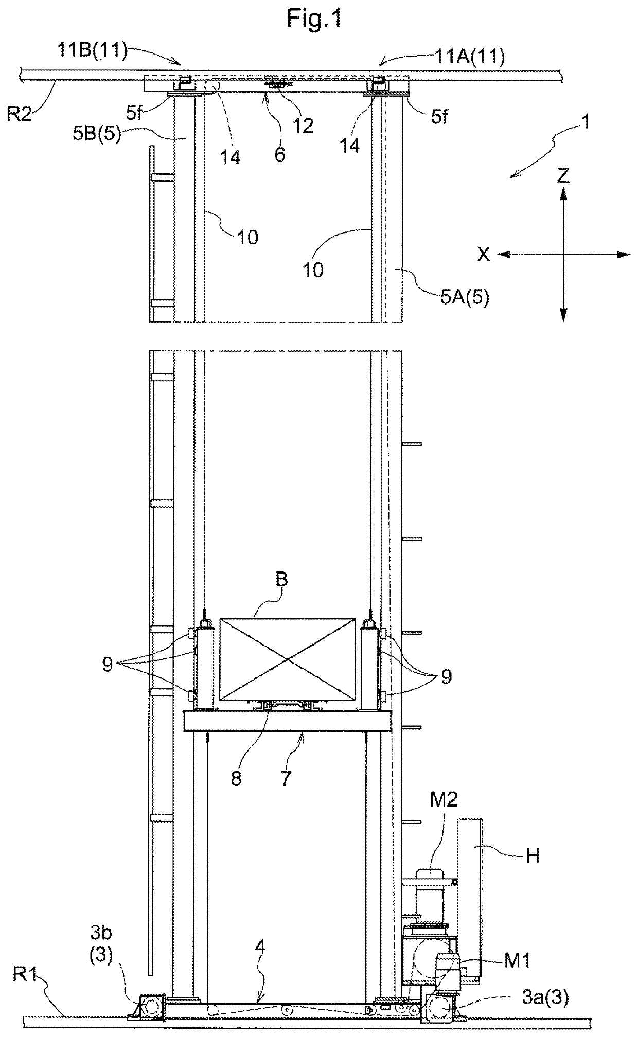
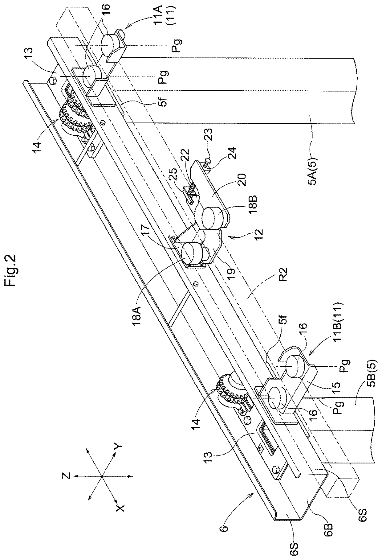
[0033]A first embodiment of the article transport apparatus will be described with reference the drawings. As shown in FIG. 1, an article transport apparatus of the present embodiment includes a stacker crane 1 that travels by being guided by a lower rail R1 installed on a floor surface and extending linearly, and an upper rail R2 disposed parallel to the lower rail R1 and extending linearly.

[0034]The stacker crane 1 includes: a traveling body 4 that supports traveling wheels 3 that roll on the lower rail R1; a pair of masts 5 (a first mast 5A and a second mast 5B) that are spaced apart from each other in a traveling direction (the direction indicated by X in FIG. 1; hereinafter referred to as “traveling direction X”) above the traveling body 4 and provided upright along an vertical direction (the direction indicated by Z in FIG. 1; hereinafter referred to as “vertical direction Z”); an upper frame 6 that connects the upper end portions of the first mast 5A and the second mast 5B to...

second embodiment

[0062]A second embodiment of the article transport apparatus will be described with reference to FIGS. 6 and 7. The present embodiment is different from the first embodiment described above in that a rotational resistance imparting device 40 is provided in a braking unit 12. The following description is focused on the difference between the article transport apparatus of the present embodiment and that of the first embodiment. The components that are not specifically described are the same as those of the first embodiment, and are denoted by the same reference numerals, with the detailed description thereof omitted.

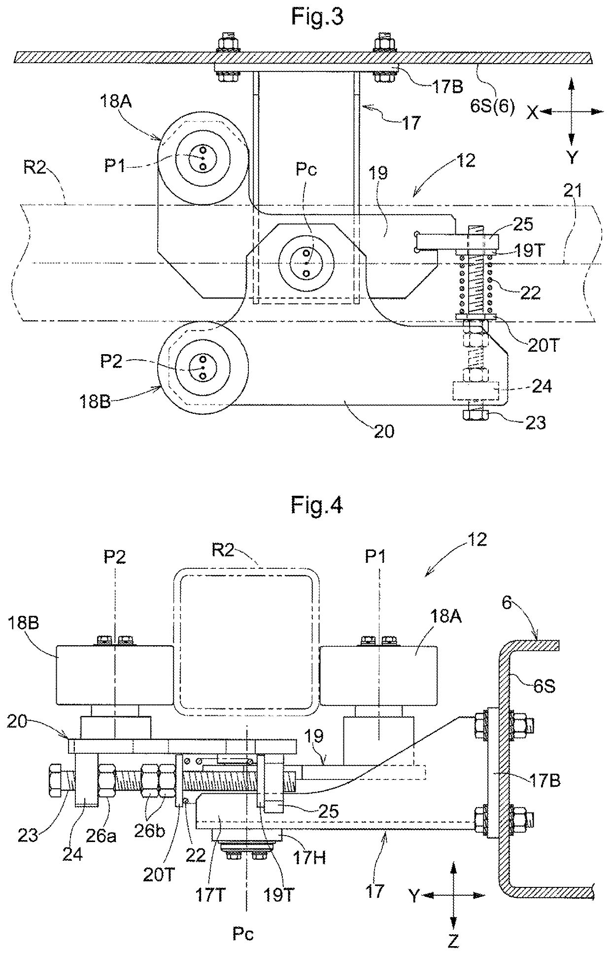
[0063]As shown in FIG. 6, a braking unit 12 according to the present embodiment is configured by adding, to the braking unit 12 (see FIG. 4) according to the first embodiment described above, a rotational resistance imparting device 40 that imparts a rotational resistance. The rotational resistance imparting device 40 is provided on a rotation shaft 30 of at least one of ...


PUM


Abstract

An article transport apparatus includes a mast provided upright on the traveling body, an upper frame (6) coupled to an upper end portion of the mast and an upper rail (R2) that guides movement of the upper frame (6). Separately from guide rollers disposed on lateral opposite sides of the upper rail (R2), a first roller (18A) and a second roller (18B) that are rotatable about vertical axes (P1, P2) are disposed on opposite sides of the upper rail (R2). A first supporting member (19) supporting the first roller (18A) is attached so as to be biased by a first biasing body (22) in a direction to push the first roller (18A) against the upper rail (R2), and a second supporting member (20) supporting the second roller (18B) is attached so as to be biased by a second biasing body (22) in a direction to push the second roller (18B) against the upper rail (R2).

Description

CROSS-REFERENCE TO RELATED APPLICATIONS[0001]This application is the United States national phase of International Application No. PCT / JP2017 / 014647 filed Apr. 10, 2017, and claims priority to Japanese Patent Application No. 2016-079547 filed Apr. 12, 2016, the disclosures of which are hereby incorporated in their entirety by reference.BACKGROUND OF THE INVENTIONField of the Invention[0002]The present invention relates to an article transport apparatus including: a lower rail installed on a floor surface; a traveling body configured to be guided by the lower rail and to travel along the lower rail; a mast provided upright on the traveling body; an upper frame coupled to an upper end portion of the mast; an upper rail extending along a traveling direction of the traveling body and configured to guide movement of the upper frame; and an elevating body including a transfer device for transferring an article and configured to move up and down along the mast, the upper frame including at...

Claims


Application Information

Patent Timeline
Patent Type & Authority Patents(United States)
IPC IPC(8): B66F9/07B65G1/04
CPCB65G1/0407B65G1/04B66F9/072B65G2203/045B65G2203/0266B66F9/07B65G2201/02
Inventor TSUKAMOTO, KUNIHIRO
Owner DAIFUKU CO LTD
Why Eureka
Try Eureka