Vibration damping device

Inactive Publication Date: 2007-03-08
TOKAI RUBBER IND LTD
View PDF4 Cites 11 Cited by
  • Summary
  • Abstract
  • Description
  • Claims
  • Application Information

AI Technical Summary

Benefits of technology

[0044] In the present mode, by reducing the distance separating the abutting portion and the rebound stopper in the axial direction, elastic deformation of the rebound cushion rubber can be limited, thus avoiding rupture or other damage to the rebound cushion rubber caused by excessive elastic deformation. With this arrangement, durability of the rebound cushion rubber can be improved.
[0045] As will be apparent from the preceding description, the vibration damping device constructed in accordance with the present invention ensures sealing advantageously effected between the superposed faces first mounting member and the main rubber

Problems solved by technology

However, even where such a rebound stopper mechanism is provided, depending on the magnitude of the input load, it is difficult in some instances to sufficiently limit relative displacement of the first mounting member and the second mounting member.
As a result, it becomes difficult to suppress excessive deformation of the main rubber elastic body, creat

Method used


Image

  • Vibration damping device
  • Vibration damping device
  • Vibration damping device

Examples


first embodiment

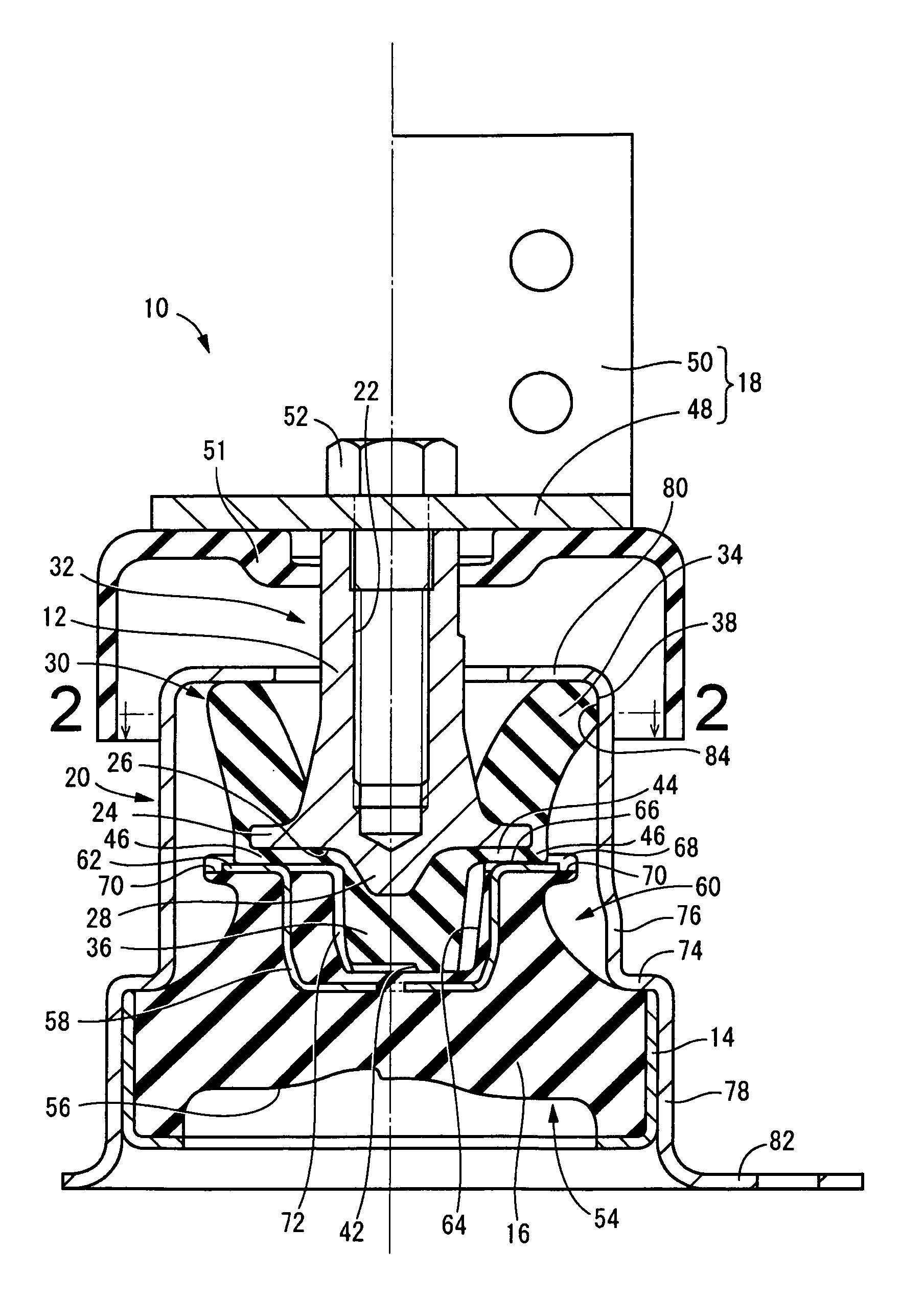
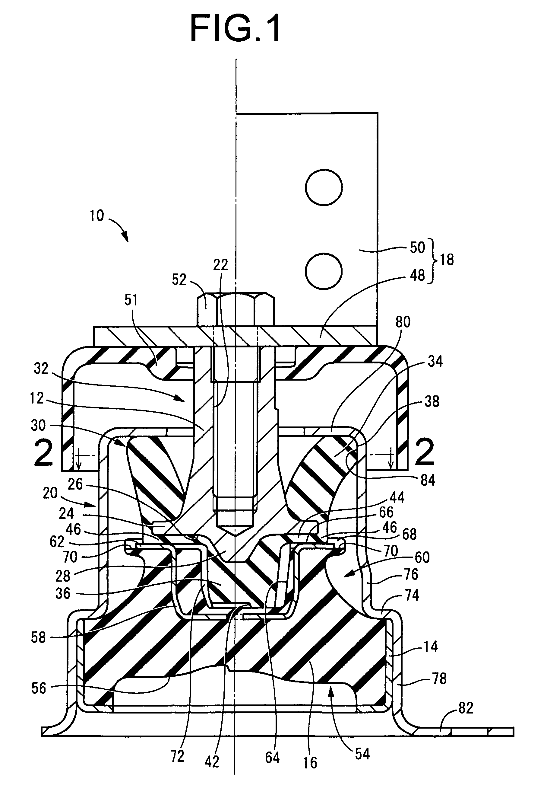
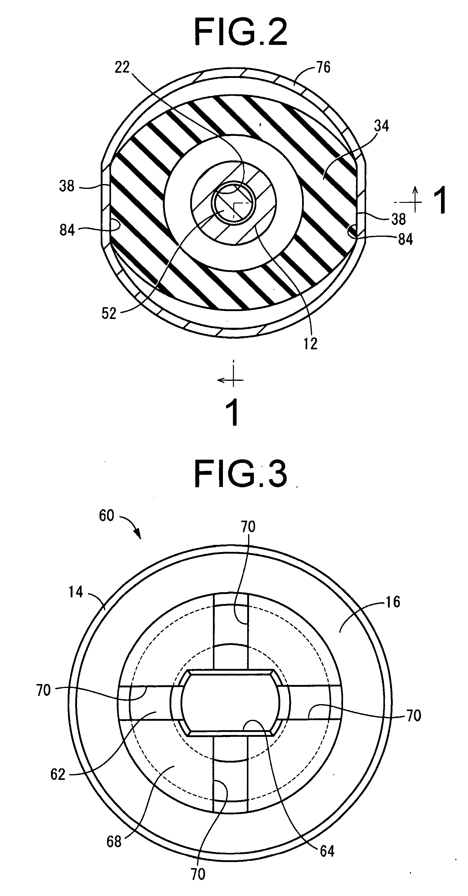
[0065]FIGS. 1 and 2 depict a vibration damping device in the form of an automotive engine mount 10 pertaining to the invention. This engine mount 10 has a structure in which a first mounting member 12 of metal and a second mounting member 14 of metal, are elastically connected together via a main rubber elastic body 16 as depicted in FIG. 3. The first mounting member 12 is fastened via a power unit-side bracket 18 to a power unit constituting a first member to be linked in a vibration damping fashion, while the second mounting member 14 is fastened via an outer bracket 20 to a vehicle body constituting the other member to be linked in a vibration damping fashion, whereby the power unit is supported in vibration damped fashion on the vehicle body. FIGS. 1 and 2 depict the engine mount 10 as it appears when not installed in an automobile. In the present embodiment, with the engine mount 10 in the installed state, the distributed support load of the power unit will be input in the axia...

second embodiment

[0166] The size, shape, construction, number, placement and other attributes of the high projecting portions 90 and low projecting portions 92 pertaining to the second embodiment hereinabove are not limited to those taught herein by way of example.

[0167] The inclined portions 94 and recessed grooves 96 pertaining to the second embodiment hereinabove are not essential, and it is possible for the high projecting portions 90 and low projecting portions 92 to connect directly with one another, for example.

[0168] Additionally, the present invention is not limited to automotive engine mounts, and may be employed favorably in body mountings or differential mountings, as well as non-automotive vibration damping devices of various kinds.


PUM


Abstract

A vibration damping device including: an elastic body of frustoconical shape; a first mounting member superposed against a small diameter end face of the elastic body; a second mounting member affixed to an outer circumferential face of a large-diameter end portion of the elastic body; and a rebound stopper mechanism for cushion-wise limitation of relative displacement of the first and second mounting members in a direction of moving apart. At least one of superposed faces of the first mounting member and the rubber elastic body is provided with a seal lip at an outside peripheral portion thereof so as to project outward therefrom and extend over an entire circumference thereof.

Description

[0001] The disclosure of Japanese Patent Applications No. 2005-256801 filed on Sep. 5, 2005, No. 2005-346961 filed on Nov. 30, 2005, and No. 2006-186268 filed on Jul. 6, 2006, each including the specification, drawings and abstract is incorporated herein by reference in its entirety. BACKGROUND OF THE INVENTION [0002] 1. Field of the Invention [0003] The present invention relates to a vibration damping device intended for installation between components to be linked in a vibration damping manner, and more particular to a vibration damping device have a first mounting member disposed separably in the axial direction from a main rubber elastic body, and furnished with a stopper mechanism for limiting relative displacement of the first mounting member and a second mounting member when excessive load is input. [0004] 2. Description of the Related Art [0005] Vibration damping devices has been used for installation between two components to be linked and supported in a vibration damping f...

Claims


Application Information

Patent Timeline
IPC IPC(8): F16F9/00
CPCF16F1/376F16F2230/02F16F3/0873
Inventor MURAOKA, MUTSUMI
Owner TOKAI RUBBER IND LTD
Why Eureka
Try Eureka