Cable connecting apparatus, cable assembly, and method of making cable assembly

Active Publication Date: 2014-06-19
HITACHI METALS LTD
View PDF7 Cites 13 Cited by
  • Summary
  • Abstract
  • Description
  • Claims
  • Application Information

AI Technical Summary

Benefits of technology

The present invention provides a cable connecting apparatus, cable assembly, and method of making cable assembly, which can collectively connect a plurality of differential signal transmission cables to a cable connector while suppressing elastic deformation of the cables to stabilize electrical characteristics. The apparatus includes ground conductors with a mounting body and an arm, first and second clamp members for clamping the ground conductors with a constant distance between them, and a distance maintaining mechanism. This allows for easy assembly of the cable assembly and stabilization of electrical characteristics. Its technical effects include suppressing elastic deformation of differential signal transmission cables and stabilizing electrical characteristics.

Problems solved by technology

However, because the shield connection terminal is crimped so as to follow the shape of the outer conductor, an insulator disposed inside the outer conductor may become elastically deformed due to a crimping force.
Accordingly, manufacturing problems, such as a change in the distance between signal line conductors inside the insulator, may occur.

Method used


Image

  • Cable connecting apparatus, cable assembly, and method of making cable assembly
  • Cable connecting apparatus, cable assembly, and method of making cable assembly
  • Cable connecting apparatus, cable assembly, and method of making cable assembly

Examples


first embodiment

[0038]Hereinafter, the present invention will be described in detail with reference to the drawings.

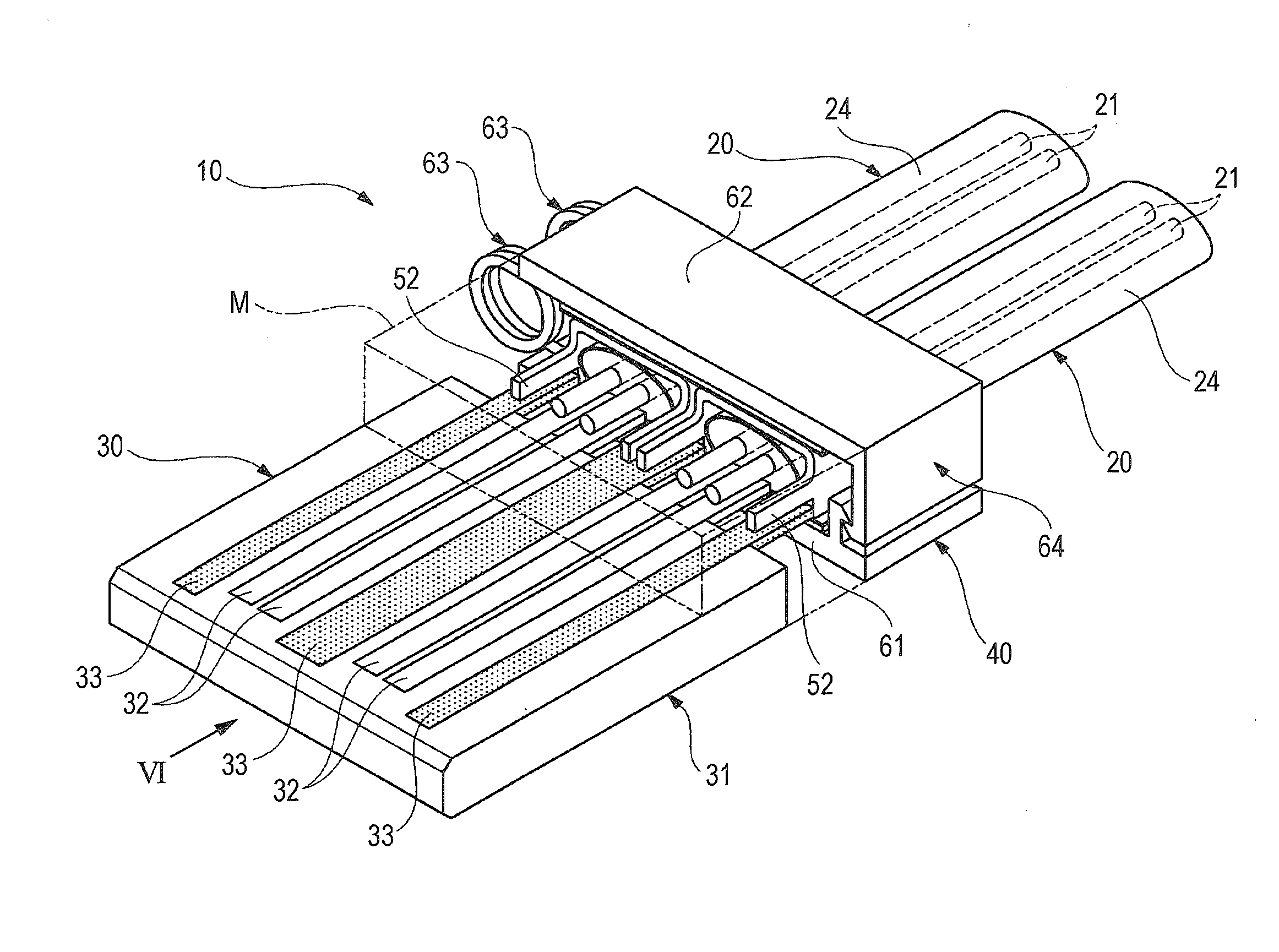
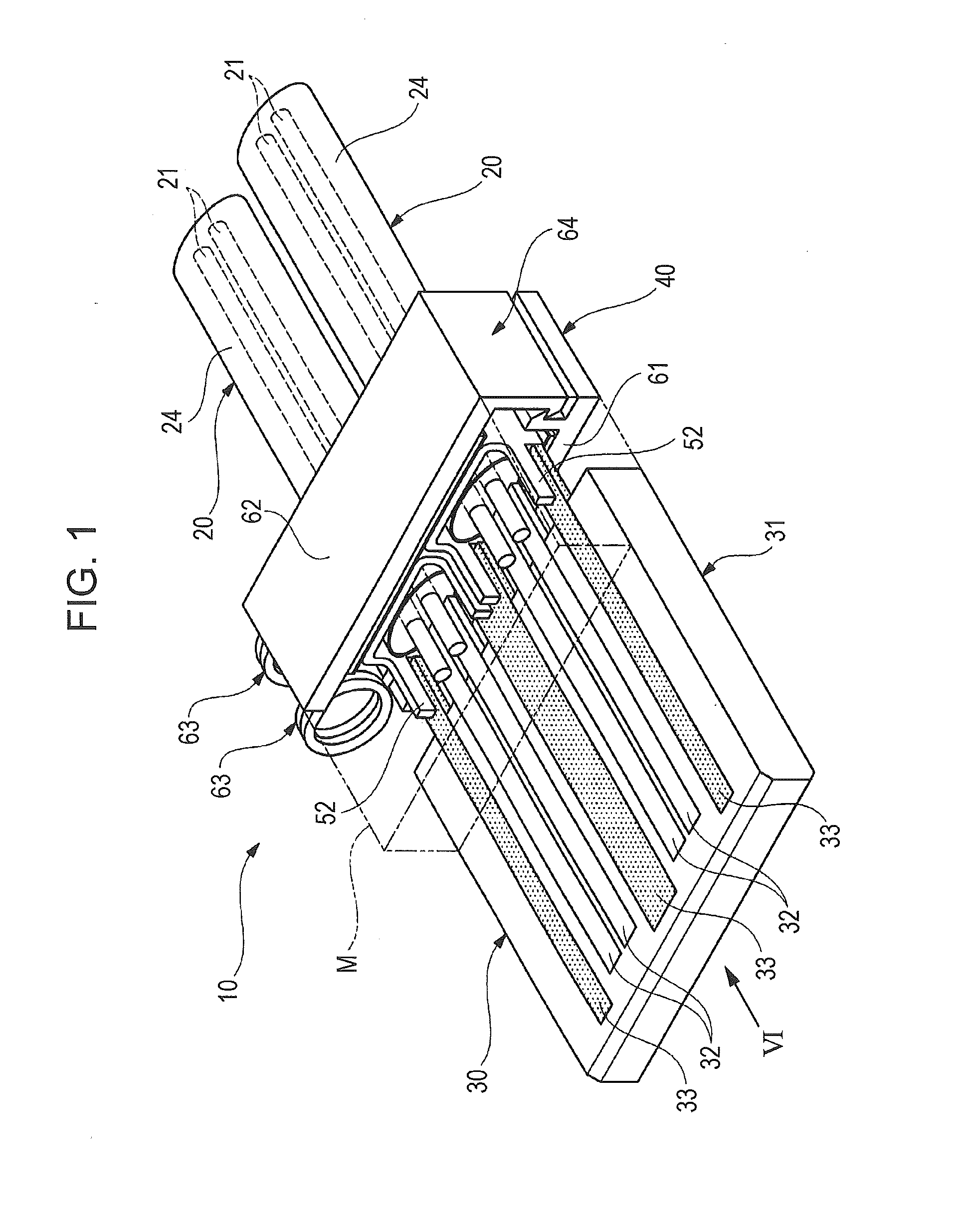
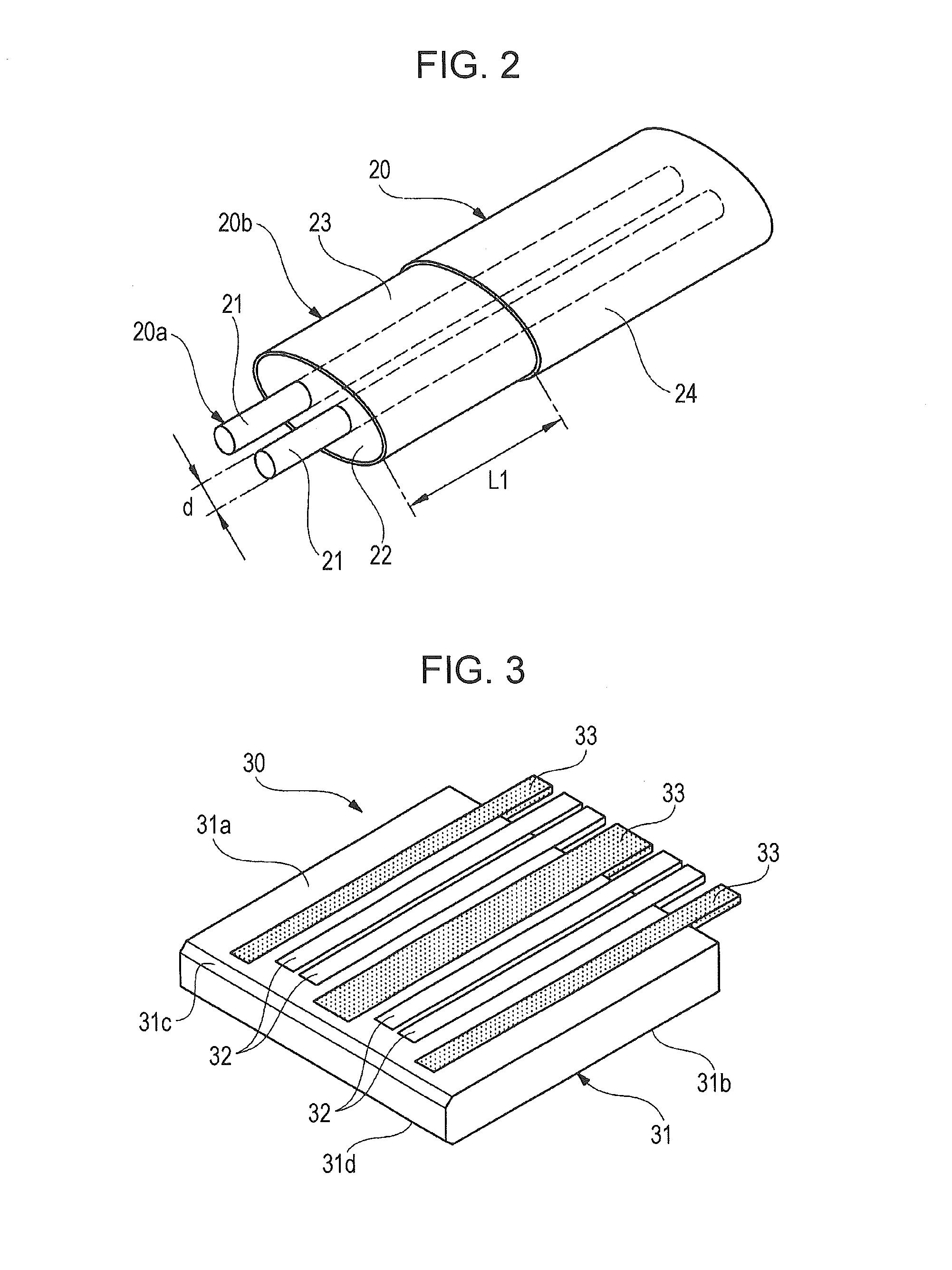
[0039]FIG. 1 is a perspective view of a cable assembly including a cable connecting apparatus according to the first embodiment. FIG. 2 is a perspective view of a differential signal transmission cable. FIG. 3 is a perspective view of a cable connector. FIG. 4 is a perspective view of a ground conductor of the cable connecting apparatus. FIG. 5 is a perspective view of a clamp mechanism of the cable connecting apparatus. FIG. 6 illustrates a subassembly of the cable assembly from which the cable connector is removed, which is seen in the direction of arrow VI in FIG. 1.

[0040]As illustrated in FIG. 1, a cable assembly 10 includes two differential signal transmission cables 20, a cable connector 30 to which the differential signal transmission cables 20 are connected, and a cable connecting apparatus 40 that collectively connects the differential signal transmission cables 20 to the cab...

second embodiment

[0082]FIG. 8 illustrates a cable connecting apparatus according to the

[0083]As illustrated in FIG. 8, a cable connecting apparatus 70 according to the second embodiment differs from the first embodiment in the following respects. First, the cable connecting apparatus 70 includes a first plate member 71 and a second plate member 72 respectively having lengths that are substantially twice larger than those of the plate members 61 and 62 (see FIG. 6). Second, the top walls 51a of four ground conductors 50 are fixed beforehand to a second copper tape 66b on the second plate member 72 with predetermined distances therebetween.

[0084]As indicated by an arrow (4) in FIG. 8, the outer conductor 23 of each of the differential signal transmission cables 20 is fitted into a corresponding one of the ground conductors 50. Then, as indicated by an arrow (5) in FIG. 8 the plate members71 and 72 are closed. Thus, an operation of assembling a cable subassembly CS1, in which the four differential sign...

third embodiment

[0087]FIGS. 9A and 9B illustrate a cable connecting apparatus according to the

[0088]As illustrated in FIGS. 9A and 9B, a cable connecting apparatus 80 according to the third embodiment differs from the first embodiment in the following respects. First, three guide protrusions 81 are provided on a surface of first plate member 61 facing the second plate member 62. Second, the ground conductors 50 are disposed in such a way that the top walls 51a of the ground conductors 50 face the first plate member 61.

[0089]The distance between the guide protrusions 81 is determined so that the ground conductors 50 can be fitted into spaces between the guide protrusions 81. Ends of the guide protrusions 81 are tapered so that the ground conductors 50 can be easily fitted into the spaces between the guide protrusions 81. As illustrated in FIG. 9A, one of the guide protrusions 81 that is positioned at the center of the guide protrusions 81 has a length smaller than that of other guide protrusions 81 ...


PUM

PropertyMeasurementUnit
Forceaaaaaaaaaa

Abstract

A cable connecting apparatus includes ground conductors, a first plate member, a second plate member, a separation torsion spring, and engagement members. The ground conductors each include a body that is to be mounted on an outer conductor of a cable, and an arm that is disposed on the body and to be connected to a ground contact of a cable connector. The first plate member and the second plate member clamp the ground conductors in a state in which the ground conductors are arranged side by side. The separation torsion spring and the engagement members are disposed between the first plate member and the second plate member and maintain a constant distance between the plate members.

Description

[0001]The present application is based on Japanese patent application No. 2012-273702 filed on Dec. 14, 2012, the entire contents of which are incorporated herein by reference.BACKGROUND OF THE INVENTION[0002]1. Field of the Invention[0003]The present invention relates to a cable connecting apparatus, a cable assembly, and a method of making the cable assembly. The cable connecting apparatus is used to collectively connect a plurality of differential signal transmission cables to a cable connector, each of the differential signal transmission cables transmitting differential signals whose phases are shifted by 180 degrees.[0004]2. Description of the Related Art[0005]Some electrical apparatuses, such as servers, rooters, storage devices, for handling high speed digital signals of several Gbit / s or higher, are compliant with a differential interface standard, such as low-voltage differential signaling (LVDS). Between such apparatuses or between circuit boards in such apparatuses, diff...

Claims


Application Information

Patent Timeline
IPC IPC(8): H01R13/58H01R43/20
CPCH01R43/20H01R13/5829H01R12/53H01R13/6585Y10T29/49174
Inventor NONEN, HIDEKI
Owner HITACHI METALS LTD
Why Eureka
Try Eureka