Micromirror and fabrication method for producing micromirror

a micromirror and fabrication method technology, applied in the direction of instruments, optical elements, data processing applications, etc., can solve the problems of increasing the overall device size, small aperture and dispersion, and high cost of liquid crystal laser beam steering devices. achieve the effect of large scanning motion and large aperture sizes

Inactive Publication Date: 2010-02-11
UNIV OF FLORIDA RES FOUNDATION INC
View PDF3 Cites 33 Cited by
  • Summary
  • Abstract
  • Description
  • Claims
  • Application Information

AI Technical Summary

Benefits of technology

[0012]Embodiments of the present invention relate to a method and apparatus for high-fill-factor micromirror beam steering. Embodiments also pertain to a method of fabricating high-fill-factor micromirrors and micromirror arrays. Embodiments of the present invention can provide high-fill-factor micromirrors by hiding at least a portion of, and preferably the entire actuating engine underneath the mirror plate of each micromirror. In a further embodiment, the hidden actuators of the actuating engine can be located close to the center of the mirror plate such that a small displacement of the actuators can generate a large scanning motion of the mirror plate. Large aperture sizes can be implemented through making the mirror plate using single-crystal silicon. According to an embodiment, the actuators and the mirror plate can be made on a single substrate.

Problems solved by technology

However, laser beam steering devices based on liquid crystals currently are expensive, have small apertures and dispersion problems, and steer over relatively narrow angles [1][2].
However, existing laser beam scanning devices have small fill factors due to the large area needed for the actuation mechanisms.
Small fill factors greatly increase the overall device size.
This becomes a serious problem for intravascular imaging.
However, large mirrors tend to have very slow scanning speeds.
If the fill factor is small, a large amount of power will be wasted.
In addition, this ‘wasted’ power may hit on the actuators of the mirrors, which can damage the mirrors.
Furthermore, thin-film Micro-Electro-Mechanical System (MEMS) mirrors tend to curl.
Electromagnetic actuation requires external magnets, which complicates device packaging.
Electrostatically-actuated micromirrors can be difficult to scale up.
Most micromirror designs are based on electrostatic actuation, which results in high driving voltages and small actuation ranges.
However, most of these micromirrors rotate about a hinge at the end of the mirror plate, so the optical center of rotation shifts during the mirror tilting.
This center shift generates an optical phase delay and a lateral shift of the optical beam on the target.
Furthermore, these mirrors have very small fill factors.

Method used


Image

  • Micromirror and fabrication method for producing micromirror
  • Micromirror and fabrication method for producing micromirror
  • Micromirror and fabrication method for producing micromirror

Examples


Embodiment Construction

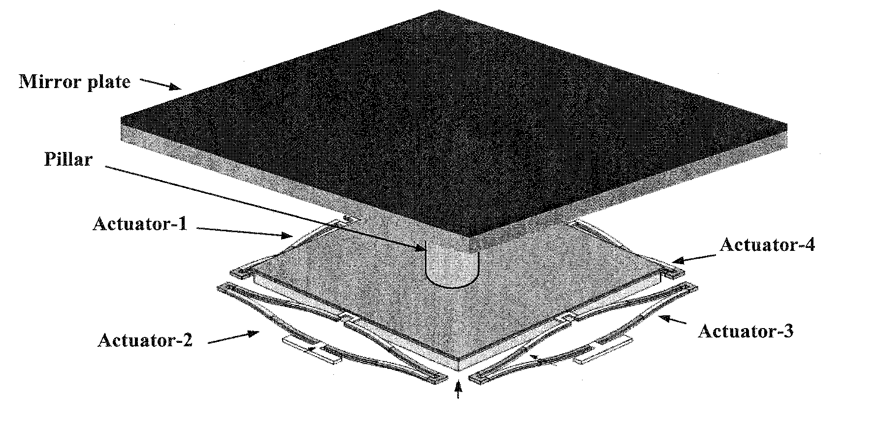
[0026]Embodiments of the present invention relate to a method and apparatus for high-fill-factor micromirror beam steering. Embodiments also pertain to a method of fabricating high-fill-factor micromirrors and micromirror array. According to an embodiment, the micromirror can have multi-degree-of-freedom motion control. In a farther embodiment, a large scanning range can be implemented. Advantageously, embodiments of the present invention can provide both a large scanning range and high fill factors. In one embodiment, process integration can be accomplished to fabricate the subject micromirrors without assembling multiple separate components.

[0027]According to an embodiment, at least a portion of, and preferably the entirety of the actuators for a micromirror can be located underneath the mirror plate. Accordingly, embodiments can provide high fill factors. In one embodiment, fill factors can be greater than 90%. In a specific embodiment, the fill factor can be limited by only the ...


PUM


Abstract

A high-fill-factor and large-aperture tip-tilt micromirror array is disclosed. Electrothermal actuation can be used to obtain a large scan range, and the actuation engine can be hidden underneath the mirror plate for high fill factor. In one embodiment, inverted-series-connected (ISC) bimorph actuators can be used to achieve tilt and piston scanning. Embodiments can be used to implement optical phased array technology for steering active and passive electro-optical systems based on MEMS mirrors.

Description

CROSS-REFERENCE TO RELATED APPLICATION[0001]The present application claims the benefit of U.S. Provisional Application Ser. No. 61 / 085,752, filed Aug. 1, 2008, which is hereby incorporated by reference herein in its entirety, including any figures, tables, or drawings.[0002]The subject invention was made with government support under a research project supported by U.S. Air Force Grant No. FA9550-08-0292.BACKGROUND OF INVENTION[0003]Laser beam steering is the precise and controllable delivery of laser beams or other guided modes to a desired location. Image sensing, laser displays, and optical switches are examples of applications that utilize laser beam steering. Currently, laser beam steering is required in a broad variety of applications including optical displays, communications, biomedical imaging, space, battlefields, surveillances, and homeland security.[0004]To accomplish laser beam steering, liquid crystals may be used. However, laser beam steering devices based on liquid c...

Claims


Application Information

Patent Timeline
Patent Type & Authority Applications(United States)
IPC IPC(8): G02B26/10G02B26/08H01L21/50
CPCG06Q10/06G06Q40/12G06Q30/0601G06Q10/06313
Inventor XIE, HUIKAIMALEY, SARAHMCMANAMON, PAULNELSON, THOMASWU, LEIPAIS, ANDREAJIA, KEMIAO
Owner UNIV OF FLORIDA RES FOUNDATION INC
Why Eureka
Try Eureka