Image Forming System

a technology of image forming and network selection, which is applied in the direction of digital output to print units, instruments, electrographic processes, etc., can solve the problems of difficulty for users to easily and quickly select one of image forming apparatuses on the network, and achieve the effect of easy and quick selection, easy and quick management of remaining amounts of toner

Active Publication Date: 2010-03-25
KYOCERA DOCUMENT SOLUTIONS INC
View PDF7 Cites 19 Cited by
  • Summary
  • Abstract
  • Description
  • Claims
  • Application Information

AI Technical Summary

Benefits of technology

[0009]The present invention relates to an image forming system which allows a user to easily and quickly select a desired image forming apparatus from among a plurality of image forming apparatuses on a network for printing a document. The present invention further relates to an image forming system which allows a manager to easily and quickly manage remaining amounts of toner for a plurality of image forming apparatuses on the network.

Problems solved by technology

In the techniques described above, therefore, it is difficult for a user to easily and quickly select one of image forming apparatuses on the network.

Method used


Image

  • Image Forming System
  • Image Forming System
  • Image Forming System

Examples


first embodiment

[0027]FIG. 4 is a schematic diagram of a configuration of an image forming system according to a first embodiment of the present invention.

[0028]In the image forming system, image forming apparatuses 201 to 204, PC 301 and PC 302, and a management apparatus40 are connected to a local area network (LAN) 10. Image forming apparatuses 201 to 204 can be selectively used from PC 301 and PC 302. The management apparatus 40 collects various types of information, such as information regarding users of the image forming apparatuses 201 to 204, the number of sheets to be used, the remaining amounts of toner, and the occurrence of an error, via the LAN 10 so that the management information can be centralized. Further, among the various types of information collected by the management apparatus 40, apparatus status information such as the remaining amounts of toner and the occurrence of an error, apparatus identifying information, and apparatus performance information are transferred to PC 301 ...

second embodiment

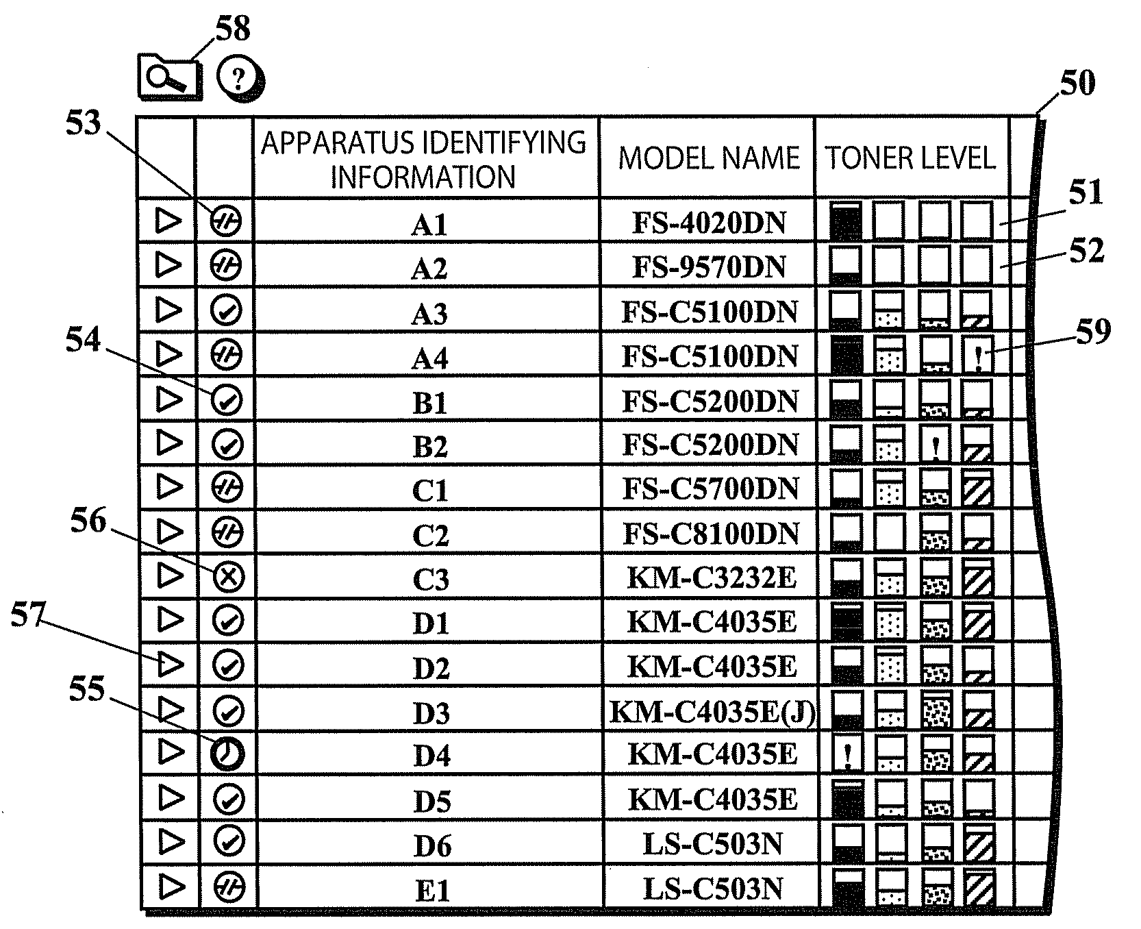
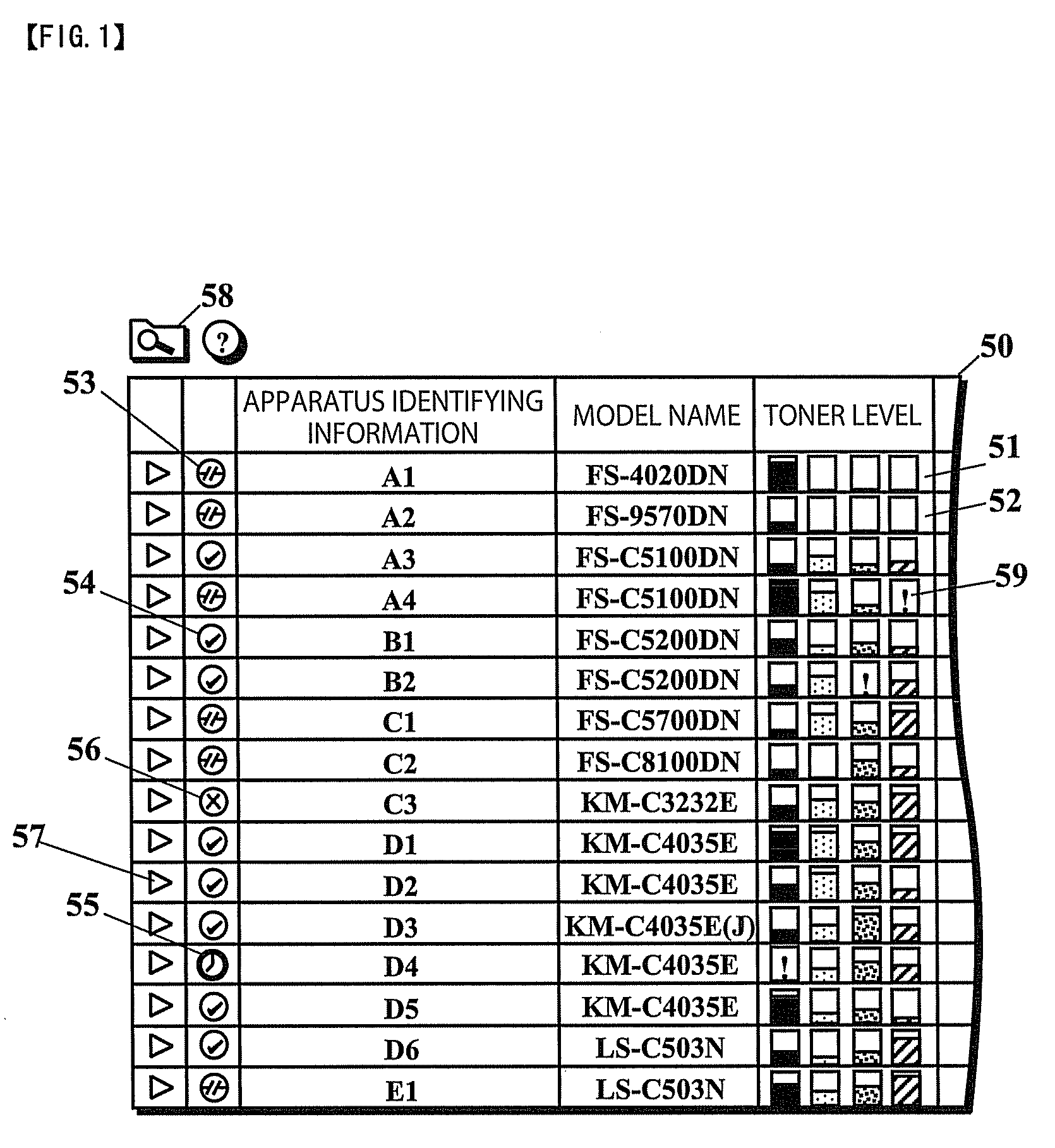
[0072]FIG. 7 is a display screen 50A on which various types of information regarding each of the plurality of image forming apparatuses obtained from the image forming apparatuses via a network is displayed according to a second embodiment of the present invention. The display screen 50A corresponds to the display screen 50 illustrated in FIG. 1.

[0073]In the display screen 50A, when an image forming apparatus is disconnected from a network or is in an abnormal state, icons representing toner levels for the image forming apparatuses are grayed out (display inactive). This allows a user to select an image forming apparatus without referring to apparatus state icons 53 to 56.

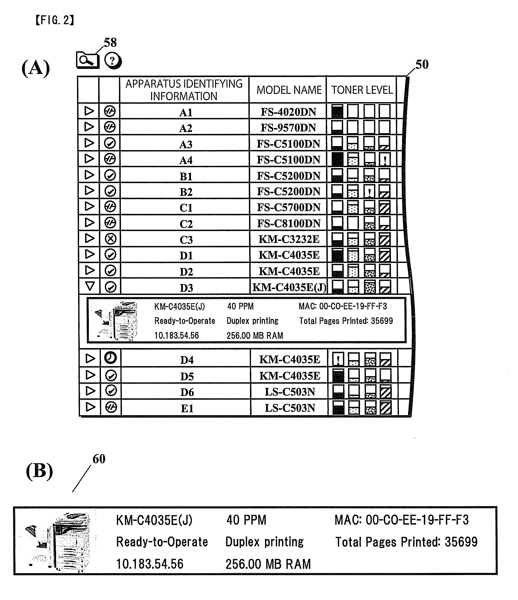
[0074]The present configuration is similar to that of the first embodiment described above. That is, when an expansion icon 57 is clicked on, detailed performance information can be displayed in an accordion-like fashion similar to that of the first embodiment.

third embodiment

[0075]FIG. 8 is a display screen 50B on which various types of information regarding each of the plurality of image forming apparatuses obtained from the image forming apparatuses via a network is displayed according to a third embodiment of the present invention. The display screen 50B corresponds to the display screen 50A illustrated in FIG. 7.

[0076]In the display screen 50B, for each image forming apparatus, a portion of apparatus performance information is displayed so as to be aligned with icons representing C / M / Y / K toner levels. The display screen 50B includes, as device performance information, color / monochrome (C / M) printing speed (which is expressed in PPM), and availability of finishing-process functions (punching and stapling functions).

[0077]For an image forming apparatus that is ready to operate, an estimated value of print waiting time, which is expressed in minutes (m), is further displayed. Furthermore, apparatus state icons are aligned in a column adjacent to the co...


PUM


Abstract

An image forming system includes a plurality of image forming apparatuses and an information processing apparatus connected to a network. Each image forming apparatus includes a remaining-toner sensor for detecting remaining amounts of toner in cyan (C), magenta (M), yellow (Y), and black (K) toner cartridges. The information processing apparatus includes (i) a storage device for storing various types of information obtained from the image forming apparatuses, including apparatus status information such as the remaining amounts of toner, and (ii) a display device for displaying icons representing the remaining amounts of C/M/Y/K toners in a line on a respective apparatus basis, and displaying the icons representing the remaining amounts of C/M/Y/K toners for all of the plurality of image forming apparatuses in lines on a respective color basis so that said lines are perpendicular to said line in which the icons representing the remaining amounts of toner are displayed.

Description

INCORPORATION BY REFERENCE[0001]This application is based upon and claims the benefit of priority from the corresponding Japanese Patent Application No. 2008-246641, filed Sep. 25, 2008, the entire contents of which is incorporated herein by reference.BACKGROUND[0002]1. Field of the Invention[0003]The present invention relates to an image forming system.[0004]2. Description of the Related Art[0005]In an image forming system in which a plurality of image forming apparatuses and a personal computer (PC) are connected via a network, one of the image forming apparatuses can be selected using the PC. In this case, a user can do a wide range selection of image forming apparatuses, which allows the user to easily and quickly select one of the image forming apparatuses.[0006]For example, when a user wishes to immediately print a large number of color images containing a large amount of magenta, the user may wish to easily and quickly search for an image forming apparatus with a high process...

Claims


Application Information

Patent Timeline
Patent Type & Authority Applications(United States)
IPC IPC(8): G03G15/00
CPCH04N1/00222H04N1/00233H04N1/32529H04N1/32539G03G15/556G03G15/553G06F3/1204G06F3/1229G06F3/126G06F3/1285G03G15/5079G03G2215/00109
Inventor KUWASAKI, NAOKI
Owner KYOCERA DOCUMENT SOLUTIONS INC
Why Eureka
Try Eureka