Microscope system

a microscope and optical system technology, applied in the field of microscope systems, can solve the problems of insufficient brightness of the image on the higher magnification side, limited diameter at the entrance of the afocal variable magnification optical system, and inability to obtain sufficient brightness, etc., to achieve the effect of a large observation field of view, improved operation performance and large resolution

Active Publication Date: 2009-01-13
EVIDENT CORP
View PDF4 Cites 10 Cited by
  • Summary
  • Abstract
  • Description
  • Claims
  • Application Information

AI Technical Summary

Benefits of technology

[0017]According to the microscope of the present invention, an effective NA can be obtained by fully utilizing the diameter of the objective lens.
[0018]According to the microscope of the present invention, as the focal length of an objective lens is within a range of about 200 mm to 40 mm, a working distance about 180 mm to 20 mm can be obtained. Since a working distance of 50 mm or greater allows a observer to easily access a sample while observing the sample under a microscope, the microscope of the present invention assures an observer an easy access to a sample under microscopic observation.
[0019]Moreover, at a working distance about 20 mm, retraction of the objective lens is not necessary in each time when a sample in a container, such as a culture dish, is to be observed or when a sample is exchanged. In this way, the microscope according to the present invention demonstrates an excellent operation performance as a microscope for operation.
[0021]Moreover, in view of various operations of an observation sample such as selecting and dissecting, it is desirable that an optimal magnification suitable for each use can be selected easily and quickly in order to carry out observation and photographing of a specific part under one microscope.
[0023]According to the microscope of the present invention, it is possible to apply for further various uses by selecting suitable objective lenses in accordance with individual uses such as observing a larger field of view, obtaining a higher resolution, etc. In this case, each of the objective lenses has a substantially equal distance from an object surface to an exit end of the objective lens, and a focal position does not shift largely with exchange of the objective lenses. Therefore, operation performance can be remarkably improved.
[0024]According to the microscope of the present invention since it has a large NA (numerical aperture), while securing a long working distance and a large observation field of view, a bright fluorescence image can be obtained, especially when selection of an ecology sample is carried out by using as a marker protein (GFP etc.) which emits fluorescence, and when observing a sample for which marking of an internal organ of small animals, such as a rat, etc has been carried out. Thus, a careless overlooking of a marker can be prevented. Furthermore, since a sufficient bright fluorescence image is obtained, an increase in efficiency of operation can be attained, without making surroundings of a sample and a whole room dark when fluorescence observation is carried out.

Problems solved by technology

However, in the conventional single objective lens type stereomicroscope, due to restrictions of the distance between two right and left optical paths from an afocal variable magnification optical system to an image forming lens, etc., a diameter at the entrance of the afocal variable magnification optical system is limited to ½ or less of the effective diameter of the objective lens.
Especially, in a design where a large magnification ratio is achieved by the afocal variable magnification optical system, brightness of the image tends to be insufficient on the higher magnification side because of the lens diameter of the afocal variable magnification optical system as a limiting factor.
When a fluorescence image is observed by using an objective lens having a considerably large effective diameter compared with the afocal variable magnification optical system, in combination with an illumination system and filters for fluorescence observation, sufficient brightness cannot not be obtained although a large field of view for observation is secured.

Method used


Image

  • Microscope system
  • Microscope system
  • Microscope system

Examples


first embodiment

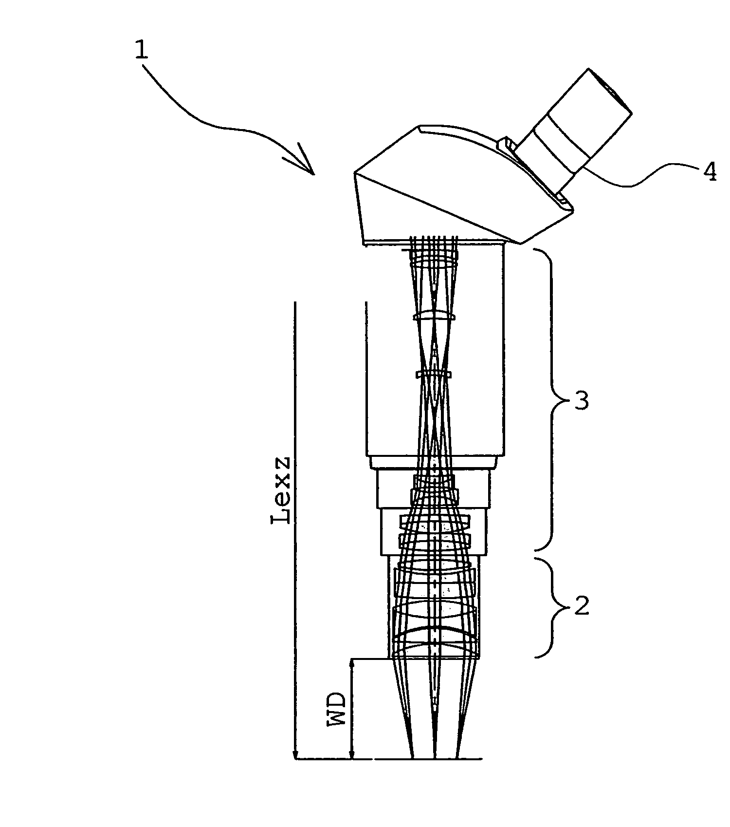
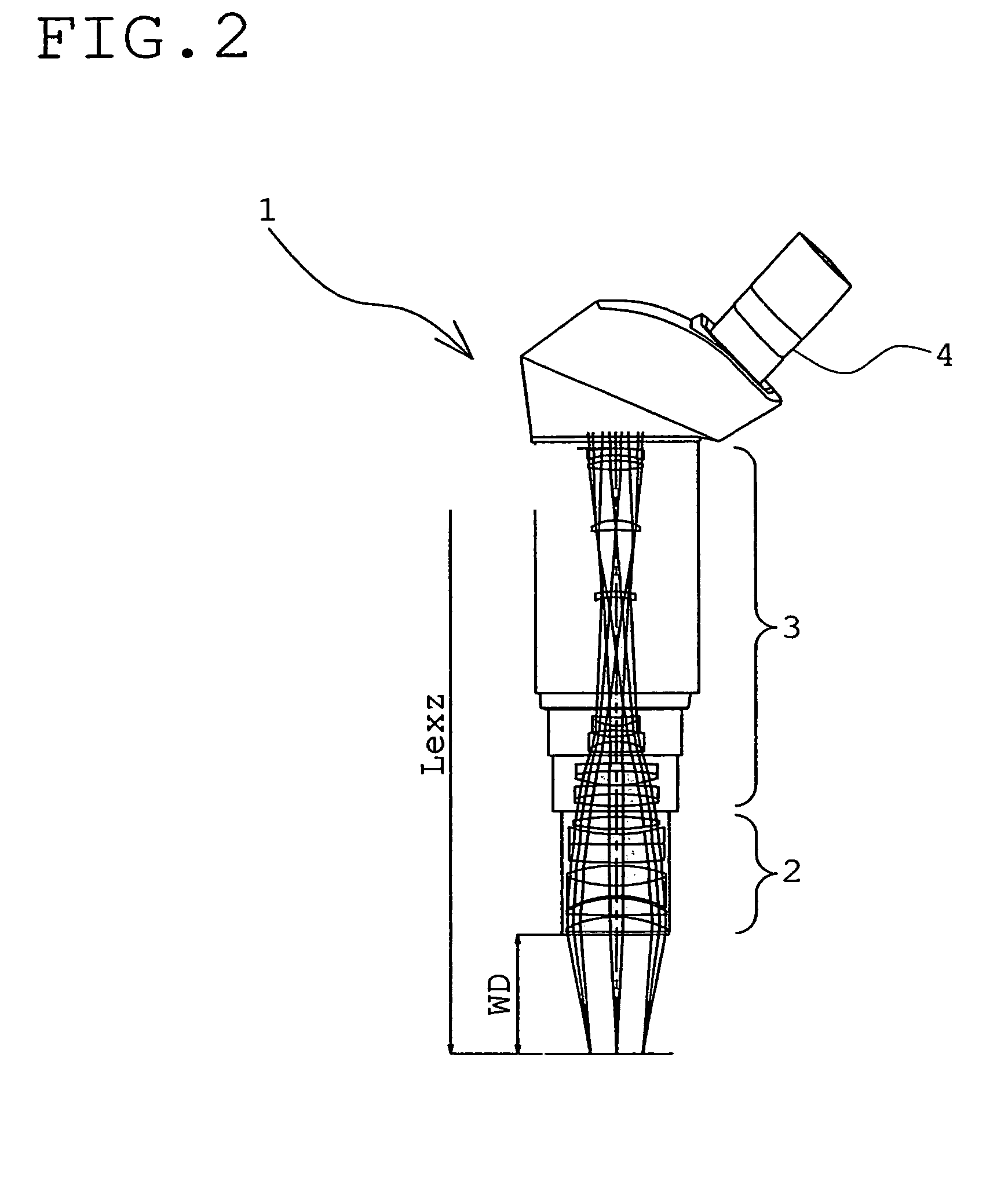
[0067]FIG. 2 is a diagram explaining an optical composition of the microscope system of the first embodiment according to the present invention.

[0068]As shown in FIG. 2, a microscope system 1 of the first embodiment is equipped with an objective lens 2 and an afocal variable magnification optical system 3, and a sample can be observed through an eyepiece 4.

[0069]As shown in FIG. 2, the microscope system of the first embodiment is constituted such that it has a long working distance WD, and a distance to the exit end of a zoom lens is suppressed moderately. In FIG. 2, Lexz is a distance from an object surface to the most distant end of the afocal variable magnification optical system. In FIG. 2, a light path diagram shows a state when the magnification of the afocal variable magnification optical system is the minimum.

[0070]In the first embodiment, the value of the condition (2) is 45, and the value of the condition (3) is 7.5. However, when values of the conditions (2) and (3) are s...

second embodiment

[0073]FIGS. 3A-3C are sectional views taken along the optical axis, showing an example of an afocal zoom lens used for the microscope system of the present invention.

[0074]FIG. 3A shows a minimum magnification state of the afocal zoom lens.

[0075]FIG. 3B shows a middle magnification state.

[0076]FIG. 3C shows a maximum magnification state.

[0077]As shown in FIGS. 3A-3C, the a focal zoom lens 5 has a plurality of lens groups G1, G2, G3, G4, G5, and G6, wherein magnification can be changed by changing a distance from an object surface to each of these lens groups G1 to G6.

[0078]FIGS. 3A-3C show that the diameter of an exit pupil becomes the maximum when the magnification is the minimum, and the diameter of then exit pupil becomes the minimum when the magnification is the maximum.

[0079]The second embodiment shows a case where ENP (max)=45 and the full length is 190. When ENP(max) is reduced until it becomes 30, the full length becomes 127. The afocal zoom lens 5 can be combined with, for ...

third embodiment

[0086]In FIGS. 6A to 6D, examples of an objective lens combined with the microscope system according to the present invention are shown. A light path diagram shown in each of FIGS. 6A-6D shows a state where the magnification of an afocal variable magnification optical system is the minimum, and an observation range becomes the maximum. An objective lens 7a shown in FIG. 6A has a lens group G9 having negative power, a focal length of which is longer than the full length of a lens, and a lens group G10 having positive power. Objective lenses 7b to 7d have focal lengths which are shorter than the full lengths of the respective objective lenses, and include, respectively, lens groups G11, G14 and G17 each having positive power, lens groups G12, G15 and G18 each having weak power, and lens groups G13 G16, and G19 each composed of a meniscus lens with a convex surface being directed to the object side and a positive single lens.

[0087]As shown in FIGS. 6A to 6D, in any of objective lenses,...


PUM


Abstract

A microscope system includes, at least, an objective lens for converting a luminous flux from an object into a parallel luminous flux, an afocal variable magnification optical system for changing a diameter of the parallel luminous flux emergent from the objective lens into a different diameter, and an image forming optical system for forming an image out of the parallel luminous flux emergent from the afocal variable magnification optical system, and the following conditions are satisfied:2·NA(ob)·FL(ob)≧30 (mm)6≦Lexz / X≦10where, NA(ob) is the maximum effective numerical aperture of the objective lens, FL(ob) is a focal length of the objective lens, X=2·NA(ob)·FL(ob), and Lexz is a distance from an object surface to the most distant end of the afocal variable magnification optical system.

Description

CROSS-REFERENCE TO RELATED APPLICATION[0001]This application is related to Japanese Application No. 2004-270010 filed in Japan on Sep. 16, 2004, the content of which is incorporated by this reference.BACKGROUND OF THE INVENTION[0002]1. Field of the Invention[0003]The present invention is related to a microscope system having excellent operation performance, bright image and variable magnification.[0004]2. Description of the Related Art[0005]Single objective lens type stereomicroscope is known as a conventional example of a microscope with excellent operation performance and extendibility. FIG. 1 is a view showing an outline composition of an optical system of such single objective lens type stereomicroscope. The objective lens of this kind of microscope has a focal length in a range of about 200 to 40 mm, and is that configured to assure comparatively low magnification for observation and a long working distance.[0006]However, in the conventional single objective lens type stereomic...

Claims


Application Information

Patent Timeline
Patent Type & Authority Patents(United States)
IPC IPC(8): G02B21/00
CPCG02B21/025
Inventor HAYASHI, KAZUHIRO
Owner EVIDENT CORP
Why Eureka
Try Eureka