
Method of and apparatus for selecting a stereoscopic pair of images

a stereoscopic and image technology, applied in the field of stereoscopic pair selection methods and apparatuses, can solve the problems of poor image quality, poor image quality, and difficulty in identifying the image,

Inactive Publication Date: 2011-09-27
SHARP KK
View PDF33 Cites 10 Cited by
  • Summary
  • Abstract
  • Description
  • Claims
  • Application Information

AI Technical Summary

Benefits of technology

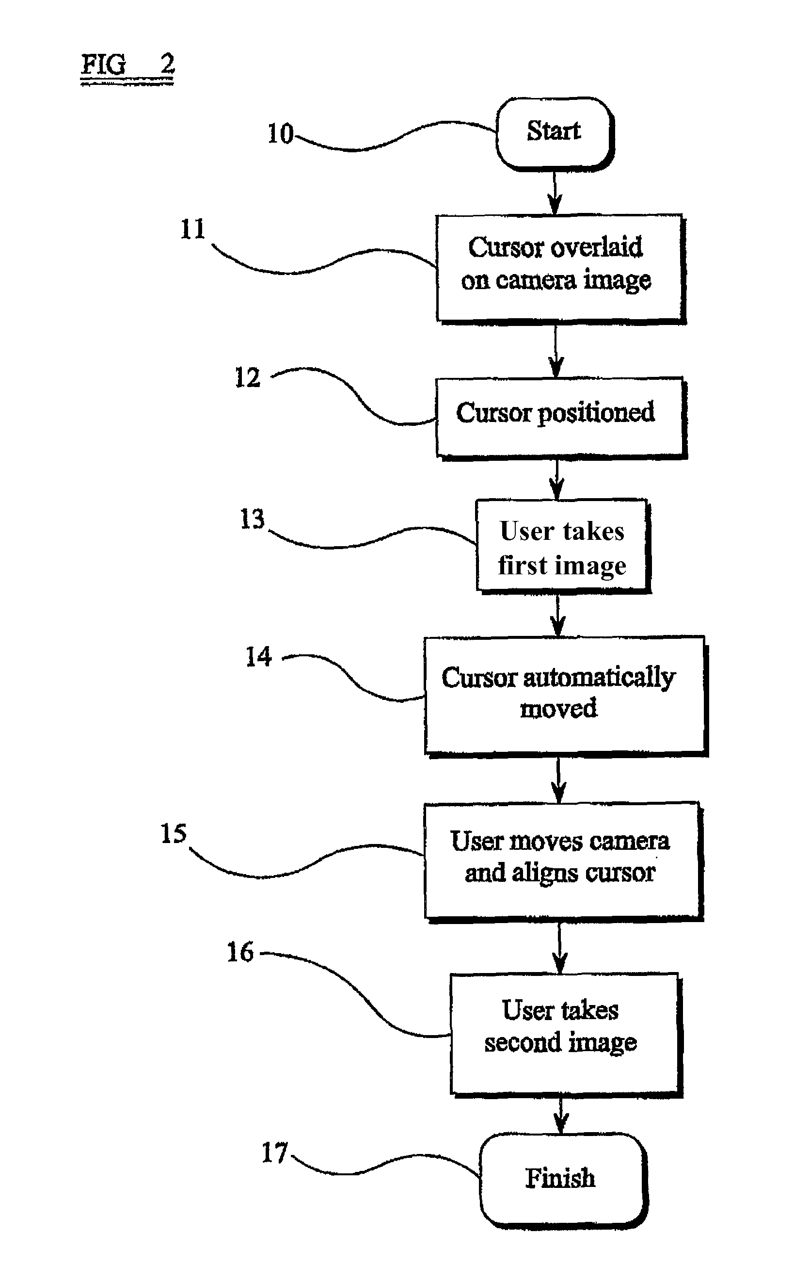
[0035]It is thus possible to provide techniques which allow a user to select stereoscopic pairs of images relatively easily and quickly. In the case of capturing images using a camera, this technique guides a user into capturing pairs of images which are substantially rectilinear and which require little or no processing before being displayed by means of a 3D display. It is not necessary for a user to attempt to match two images which are suffering from perspective distortion because of rotation of the camera between capturing the first and second images.
[0038]Position measuring sensors such as GPS (Global Positioning System), compass and tilt sensors may also be used to enhance the system and provide additional feedback to help ensure the two images are as parallel as possible.

Problems solved by technology

If the images are not rectilinear, then the stereo image will be uncomfortable to view due to vertical disparities, perspective effects, excessive depth, etc, that the HVS cannot reconcile and the 3D effect breaks down.
However if the initial pair of images are badly aligned, such algorithms will be very slow or may completely fail.
If a large amount of rectification is required, then the image quality may suffer when the two images are reprojected.
Furthermore, the image overlap between the rectified images may be reduced and less usable image area will be available for the 3D image.
However, when this technique is followed, the camera will be rotated relative to its orientation when the first image was taken so that perspective errors are introduced and the two images are not rectilinear, resulting in a 3D image of poor visual quality.
There is currently no known automated system for providing a recommendation of the separation required for producing 3D images which may be comfortably viewed.

Method used


Image

  • Method of and apparatus for selecting a stereoscopic pair of images
  • Method of and apparatus for selecting a stereoscopic pair of images
  • Method of and apparatus for selecting a stereoscopic pair of images

Examples


Embodiment Construction

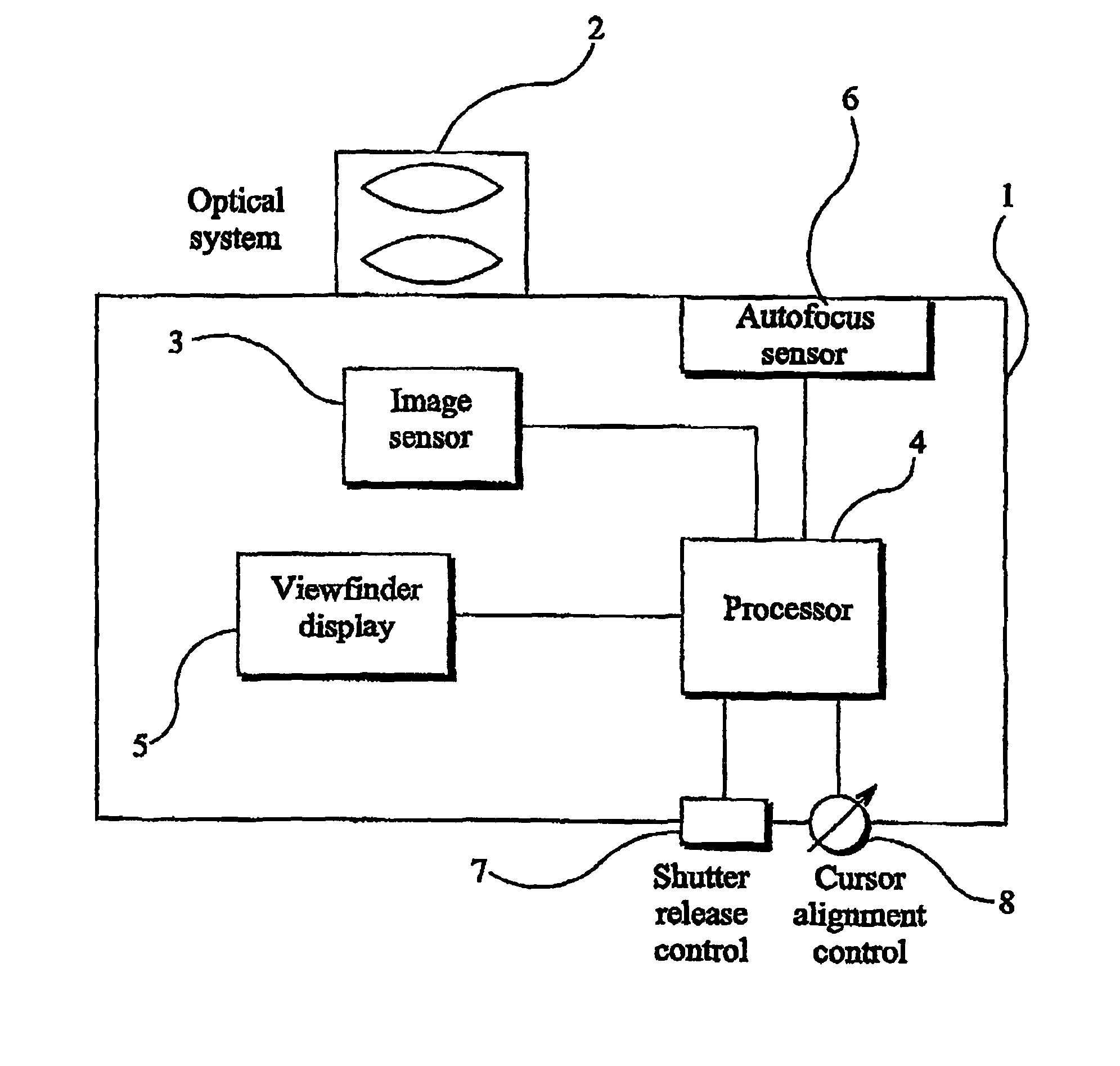
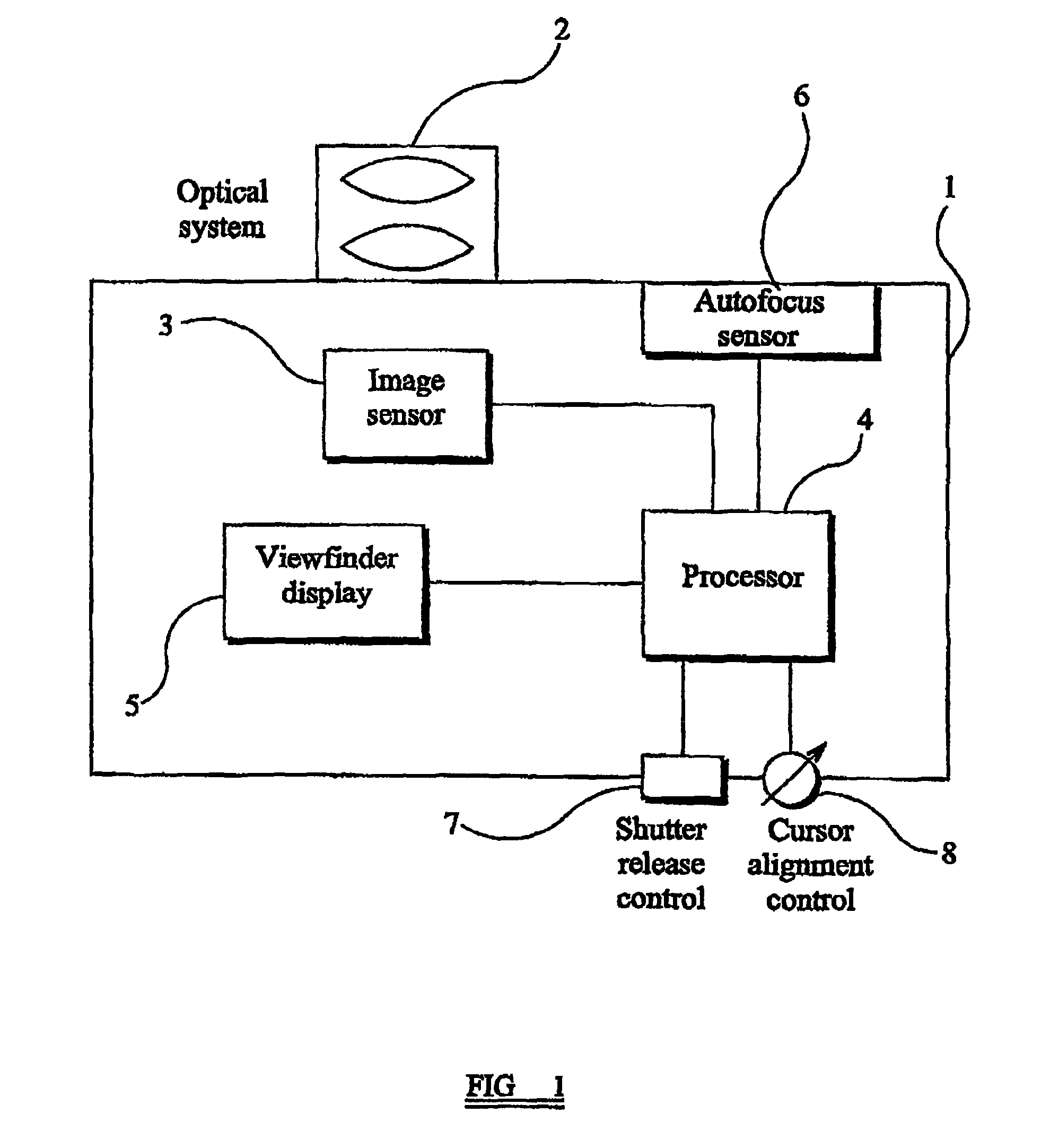
[0049]FIG. 1 illustrates an apparatus constituting an embodiment of the invention in the form of a digital “still” camera 1. The camera 1 comprises an optical system 2 of conventional type for forming an image of a scene. The camera 1 also comprises a conventional image sensor 3 on which the image is formed and which converts the optical image into corresponding electrical signals. The output of the image sensor 3 is connected to a processor 4, which processes the sensor signal in any suitable way, for example for display and subsequent printing to a hard copy. The processor 4 has an output connected to a viewfinder display 5, for example of the colour liquid crystal display (LCD) type.

[0050]The optical system 2 comprises a set of lenses and a motor or the like for adjusting the positions of the lenses or lens groups to perform focusing. The camera 1 is of the “autofocus” type and includes an autofocus sensor 6, which supplies to the processor 4 information about the distance from t...


PUM


Abstract

A method is provided for selecting a stereoscopic pair of images, for example as they are captured by a camera or from an existing collection of captured images. A first image is selected and a cursor overlaid on the first image is aligned with an image feature. The cursor is then shifted by a predetermined amount and a second image is selected such that the cursor is overlaid on the second image and is substantially aligned with the feature.

Description

TECHNICAL FIELD[0001]The present invention relates to a method of and an apparatus for selecting a stereoscopic pair of images. The present invention also relates to computer programs for such methods. Such techniques may be used, for example, in photography, videography, movie production and any application where stereoscopic images may be required. Such techniques may be used at the time of capturing stereoscopic images or may be used following capture, for example, to select stereoscopic pairs from still images or video sequences.BACKGROUND ART[0002]Three dimensional images as used in most 3D display technologies, e.g. EP 0 602 934, EP 0 656 555, EP 0 708 351, EP 0 726 482, EP 0 829 743 and EP 0 860 728 are formed by two 2D images. These displays direct separate images to either eye so that one eye sees one image and the other eye sees the other image. The Human Visual System (HVS) internally fuses the two images into a 3D image so that a person may sense depth from the displayed...

Claims


Application Information

Patent Timeline
Patent Type & Authority Patents(United States)
IPC IPC(8): H04N5/225H04N5/232H04N13/221
CPCH04N5/23293H04N13/0022H04N13/021H04N13/0221H04N13/211H04N13/221H04N13/128H04N23/635
Inventor HILL, LYNDONJONES, GRAHAM R.
Owner SHARP KK
Learn More