Flow restictor

a flow restictor and flow rate technology, applied in the direction of mixing, chemistry apparatus and processes, mechanical instruments, etc., can solve the problems of diluted solution spillage, difficulty in changing the flow rate of liquid, and difficulty in removing and replacing components, so as to achieve easy and quick selection and minimum safety risk for operators

Inactive Publication Date: 2005-05-19
JOHNSONDIVERSEY INC
View PDF5 Cites 12 Cited by
  • Summary
  • Abstract
  • Description
  • Claims
  • Application Information

AI Technical Summary

Benefits of technology

[0007] An object of the present invention is to create a liquid flow restrictor which permits an operator to easily and quickly select one of multiple differing flow restrictions corresponding to desired flow rates (e.g. dilutions) in a simple manner and with minimum safety risk to the operator.

Problems solved by technology

This method of flow regulation has several disadvantages primarily due to the fact that it is difficult to change the flow rate of liquid to be diluted in the eductor.
This is because it is difficult to remove and replace the component which carries the flow restricting channel with a flow restricting component for a different flow rate.
This involves partially dismantling the eductor, which is an onerous task and can result in spillage of the solution being diluted, indeed the operator may become exposed to the potentially hazardous solution.
Components thus removed, to change the flow rate, can be easily damaged and may be incorrectly reinstalled in the eductor, which in turn leads to other problems.

Method used


Image

  • Flow restictor
  • Flow restictor

Examples


Embodiment Construction

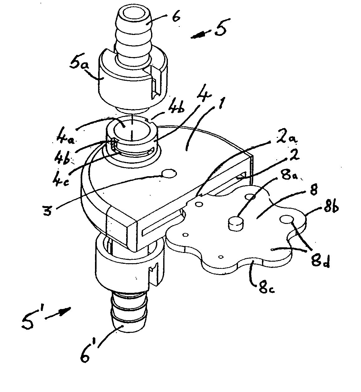
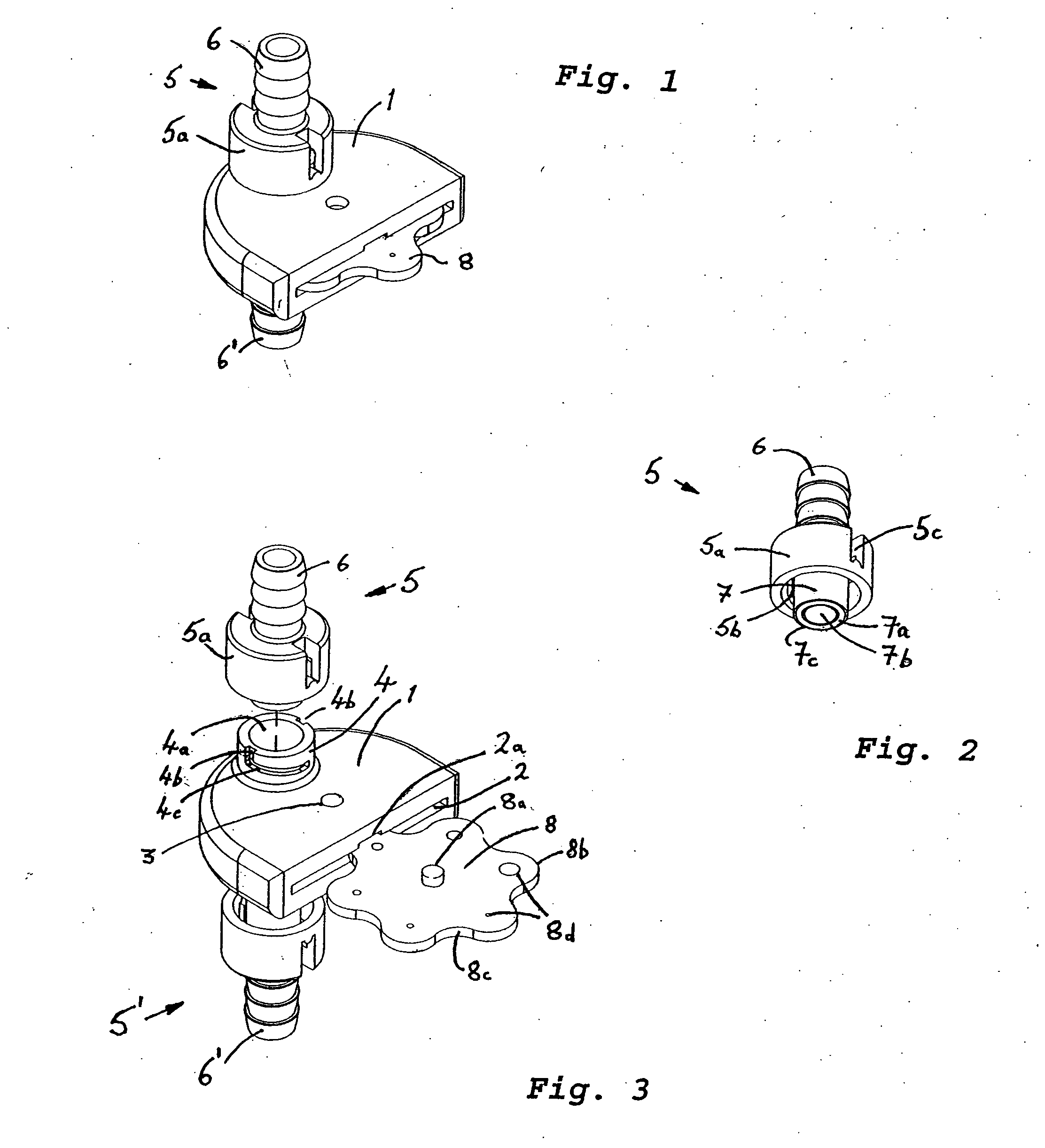
[0020] FIGS. 1 to 3 show a liquid flow restrictor embodying the invention in the form of a housing 1, on either side of which is located an opening 4a (one visible only) of a housing connector 4. Respective ends 7 of a pair of identical flow conduits 5, 5′ pass through the openings 4a, when the housing 1 and flow conduits 5, 5′ are assembled. The flow conduits 5, 5′ each have a central axial tube providing the flow path 7b and having an integral pipe connector 6, 6′ for connecting the flow restrictor in the supply pipeline of a device being supplied, such as an eductor. Around the central tube is an integrally formed skirt portion 5a. The axes of the two openings 4a are aligned with one another and the openings 4a extend from outside the housing 1, through the housing wall and into a cavity 2 within the housing 1.

[0021] The cavity 2 of the housing has a substantially flat form and opens to one side of the housing, as can be seen in FIGS. 1 and 2. The cavity 2 is sized for receiving...


PUM


Abstract

A liquid flow restrictor in the supply line of an eductor or other dilution or dispensing device has a rotatably mounted disc with opposite faces and a plurality of apertures or holes, which provide different flow restrictions between the faces, and a pair of flow conduits sealingly engaging against the faces, whereby on rotation of the member the zones are selectively brought into communication with the conduits to provide a desired flow restriction.

Description

FIELD OF THE INVENTION [0001] This invention relates to the field of liquid flow rate regulation e.g. of the liquid in the supply line of a chemical diluting device, such as an eductor or the like. BACKGROUND OF THE INVENTION [0002] It is common practice in many industries, such as hotels and catering, for chemicals such as those used for cleaning to be purchased as concentrated liquids and then diluted with water to give the correct concentrations for use. Proportioning dispensing apparatus have been designed to achieve the desired dilution of the concentrated solution and dispense the mixed diluted solution. [0003] These dispensers have commonly employed venturi-type devices, known as eductors, to aspirate or draw the concentrated solution into the water stream, see e.g. WO94 / 04857. In these eductors water travelling through a passage entrains the concentrated solution at a point where a restricted flow channel in the passage widens. [0004] In order to ensure that the solution is ...

Claims


Application Information

Patent Timeline
Patent Type & Authority Applications(United States)
IPC IPC(8): B01F15/02F16L55/00E03C1/08F16K3/08F16K3/32F16L55/10
CPCF16K3/085F16L55/10F16K3/08E03C1/08
Inventor OLIVER, STEPHEN
Owner JOHNSONDIVERSEY INC
Why Eureka
Try Eureka