Method for reconfiguring a communication network

a communication network and reconfiguration technology, applied in data switching networks, frequency-division multiplexes, instruments, etc., can solve problems such as reducing the performance of communication networks, and achieve the effect of shortening the down tim

a communication network and reconfiguration technology, applied in data switching networks, frequency-division multiplexes, instruments, etc., can solve problems such as reducing the performance of communication networks, and achieve the effect of shortening the down tim

US20100110880A1Active Publication Date: 2010-05-06SIEMENS AG

Image

  • Method for reconfiguring a communication network
  • Method for reconfiguring a communication network
  • Method for reconfiguring a communication network

Examples


Embodiment Construction

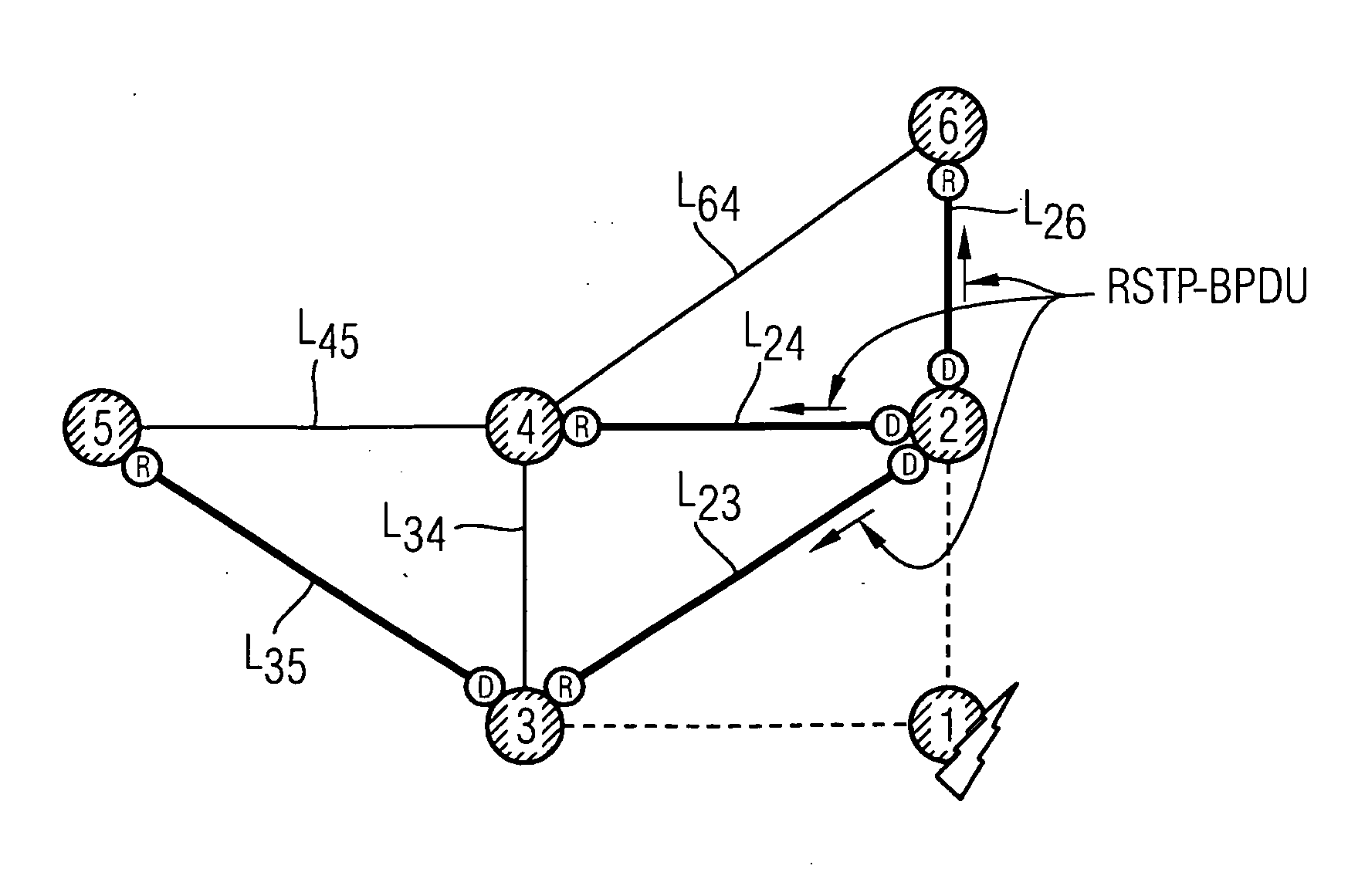
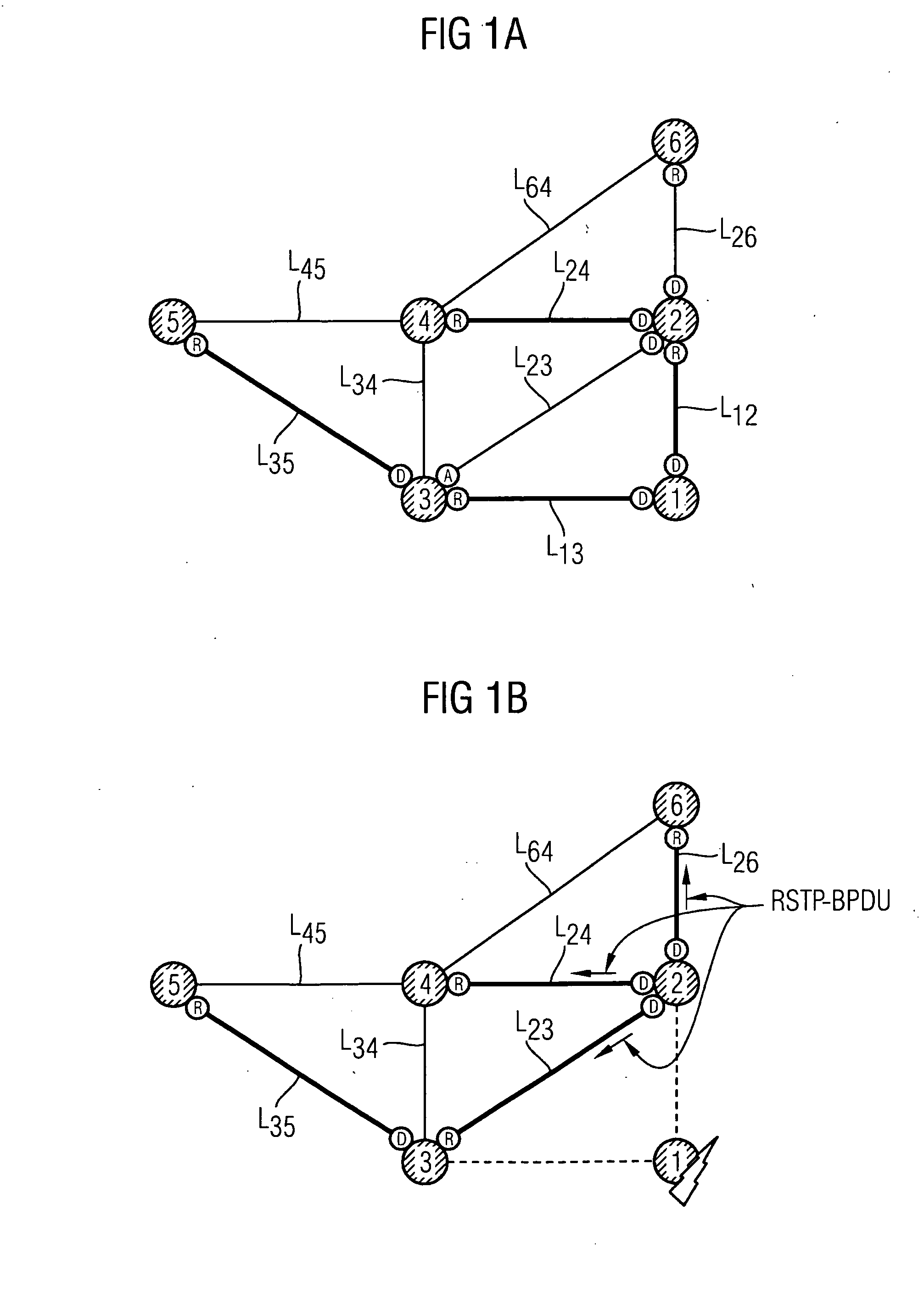
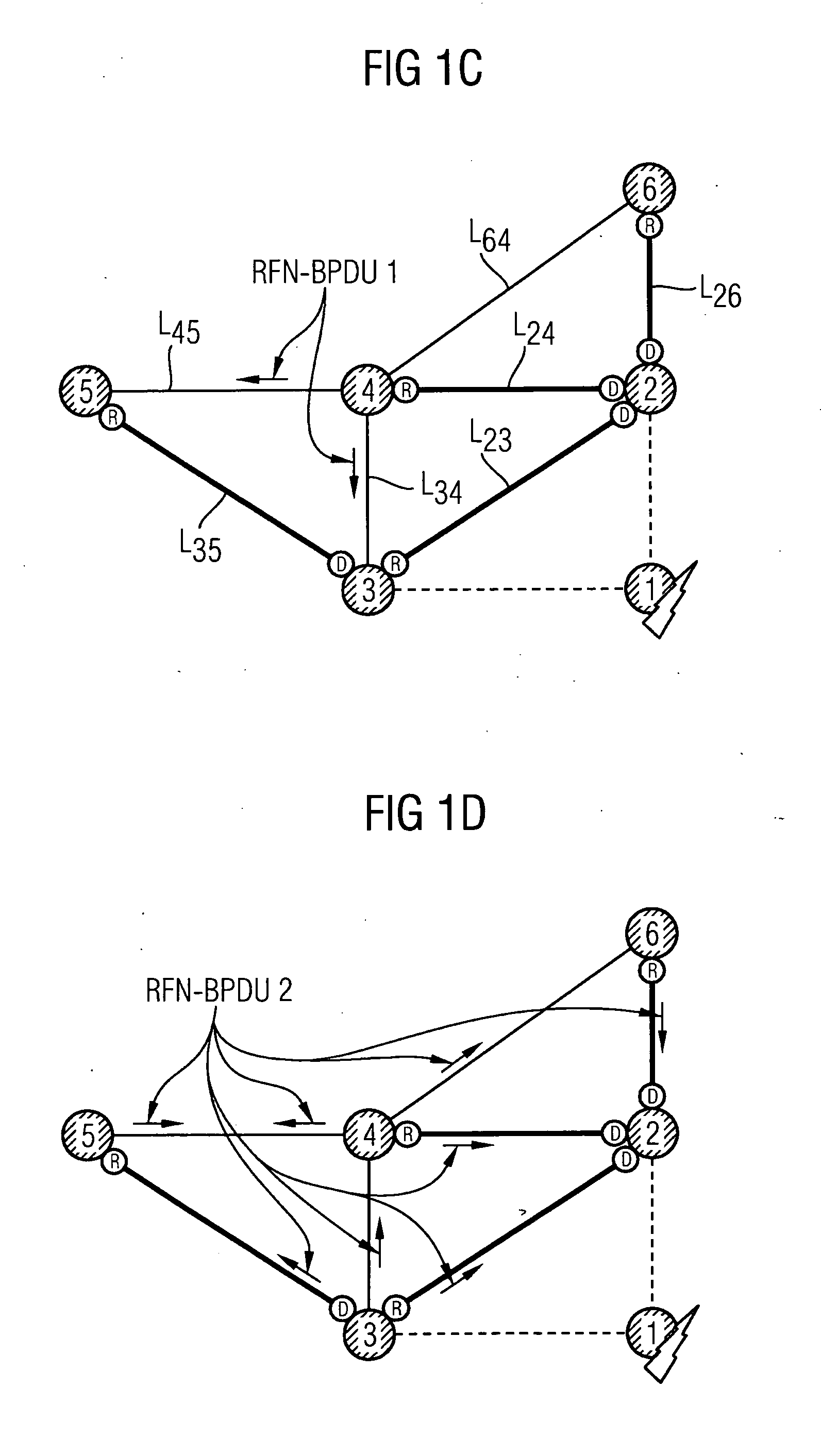
[0046]Reference will now be made to FIGS. 1A-1E, in which is shown in schematic form an exemplary embodiment of the communication network to illustrate an exemplary embodiment of the method.

[0047]The physical topology of the communication network incorporates a plurality of bridges, 1 to 6, each of which has a plurality of ports through which the bridges are connected to each other by means of (data) links L. Thus, bridge 1 is connected via a link L12 with bridge 2 and via a link L13 with bridge 3. Bridge 2 is connected via a link L26 with bridge 6, via a link L24 with bridge 4 and via a link L23 with bridge 3. Bridge 3 is connected via link L13 with bridge 1, via link L23 with bridge 2 and via a link L35 with bridge 5. Bridge 4 is connected via a link L34 with bridge 3, via link L24 with bridge 2, via a link L64 with bridge 6 and via a link L45 with bridge 5. Bridge 5 is connected via link L45 with bridge 4 and via link L35 with bridge 3. Bridge 6 is connected via link L26 with bri...


PUM


Abstract

A method for reconfiguring a packet-switched communication network using a network protocol for installing a logic topology of the network formed as a spanning tree is disclosed. The method includes detecting failure of a direct link to a root bridge of the spanning tree by a first bridge; detecting the failure of a direct link to the root bridge by a second bridge; transmitting a first configuration frame generated by the first bridge to other bridges; receiving the first configuration frame by a third bridge and transmitting a second configuration frame, generated by the third bridge, to the other bridges; detecting the first or second configuration frame by the second bridge and transmitting the third configuration frame generated by the second bridge to the other bridges; receiving the third configuration frame by the other bridges of the network and triggering a reconfiguration of the network with detection of a new spanning tree by the network protocol.

Description

CROSS REFERENCE TO RELATED APPLICATIONS[0001]This application is the US National Stage of International Application No. PCT / EP2007 / 060080 filed Sep. 24, 2007 and claims the benefit thereof. The International Application claims the benefits of European Patent Application No. 06020452.6 EP filed Sep. 28, 2006 and German Patent Application No. 10 2007 015 226.6 EP filed Mar. 29, 2007, all of the applications are incorporated by reference herein in their entirety.FIELD OF INVENTION[0002]The invention is in the technical field of packet-switched communication networks, and relates to a method for reconfiguring a communication network with a logical topology in the form of a spanning tree.BACKGROUND OF INVENTION[0003]It is possible to link with each other several packet-switched networks (LAN=Local Area Network) or segments of the one and same LAN via “intelligent” bridges or multiport bridges (switches). When this is done, the bridges can autonomously detect the logical topology of the n...

Claims


Application Information

Patent Timeline
06 May 2010
Publication
US20100110880A1
IPC
G06F11/07
CPC
H04L12/462; H04L41/0677; H04L69/40; H04L45/48; H04L45/22; H04L45/28; H04L12/14
Inventors
KULKARNI, VIVEK; SFEIR, ELIE