Buoyancy hydro power generator and method

a hydropower generator and buoyancy technology, applied in the direction of floating buildings, dynamo-electric machines, hulls, etc., can solve the problems of difficult to match the generation of power with real-time demand, difficulty in constant voltage and current supply, and inability to meet the pattern of demand for power generated from renewable sources. to achieve the effect of improving the supply of electrical power

Inactive Publication Date: 2010-05-13
BUOYANCY HYDRO
View PDF15 Cites 18 Cited by
  • Summary
  • Abstract
  • Description
  • Claims
  • Application Information

AI Technical Summary

Benefits of technology

[0008]It is therefore an object of the present invention to provide buoyancy hydro power storage and generation which improves the su

Problems solved by technology

However the generation of power from renewable sources does not usually match the pattern of demand and there is a need to store energy and use it to generate electrical power with minimum losses during peak demand periods.
There is also a need to store energy generated by conventional coal fired and nuclear power stations since even here it is difficult to match the generation of power with real time demand.
In the case of harnessing sea energy the motion of waves and currents can vary con

Method used


Image

  • Buoyancy hydro power generator and method
  • Buoyancy hydro power generator and method
  • Buoyancy hydro power generator and method

Examples


Embodiment Construction

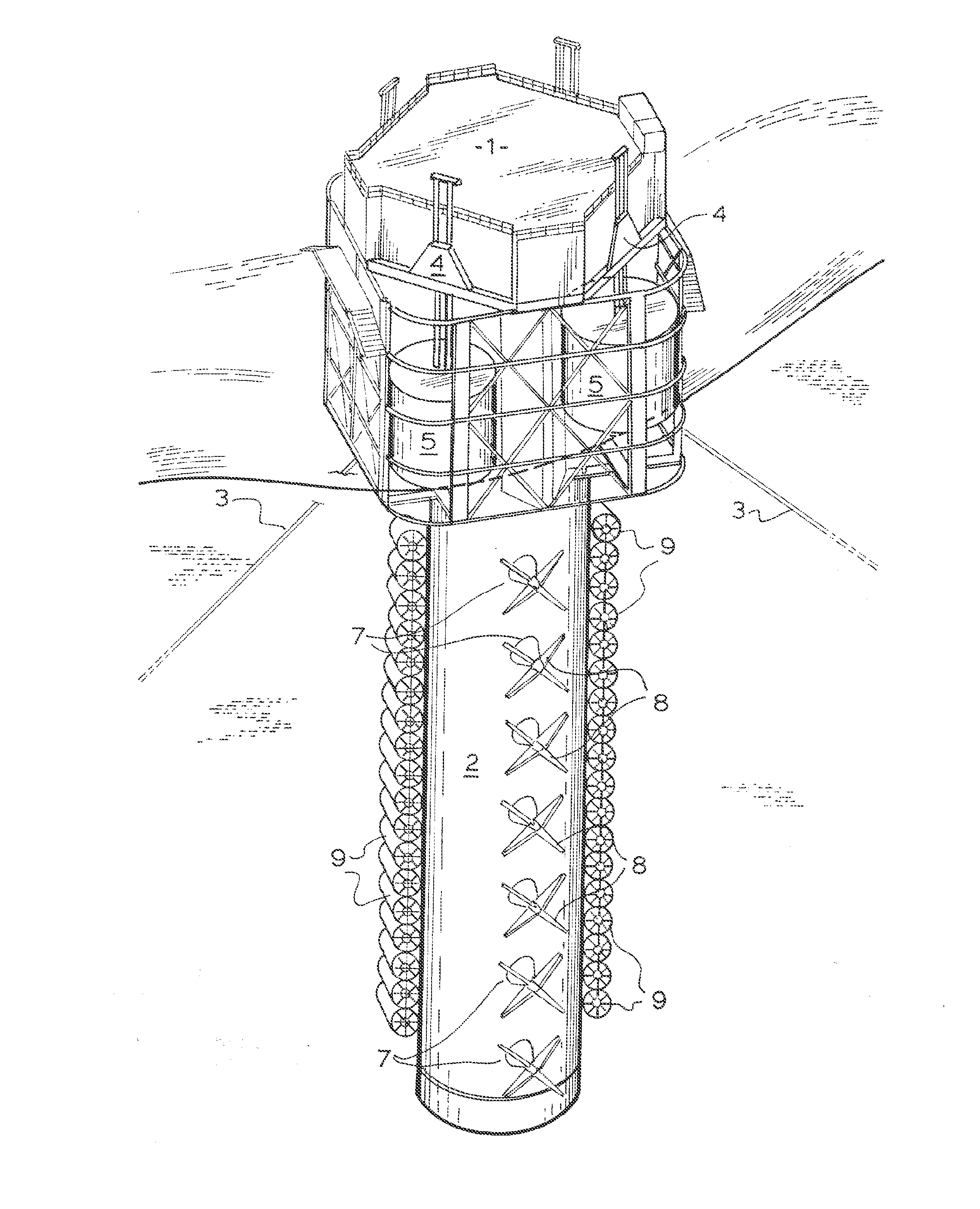
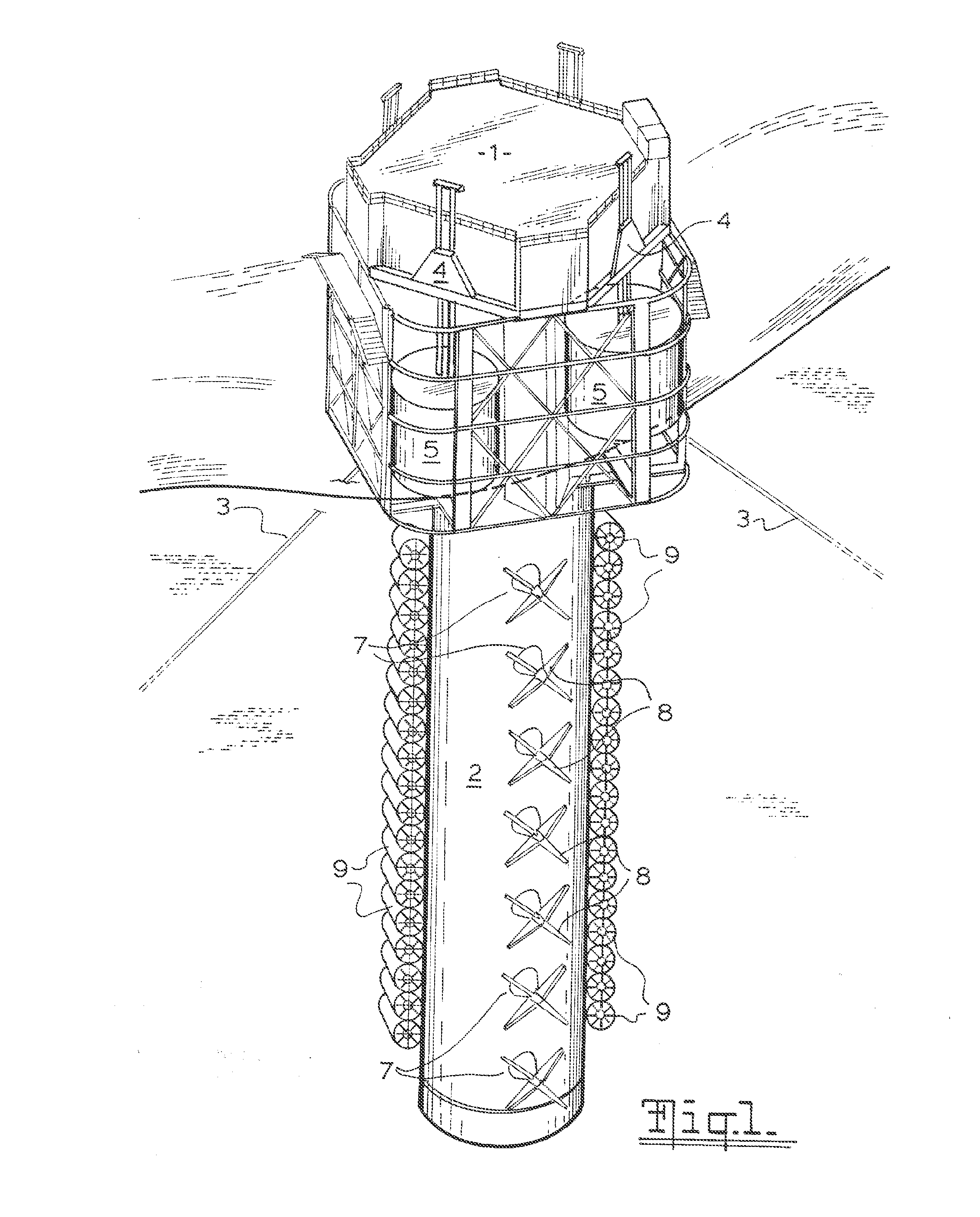
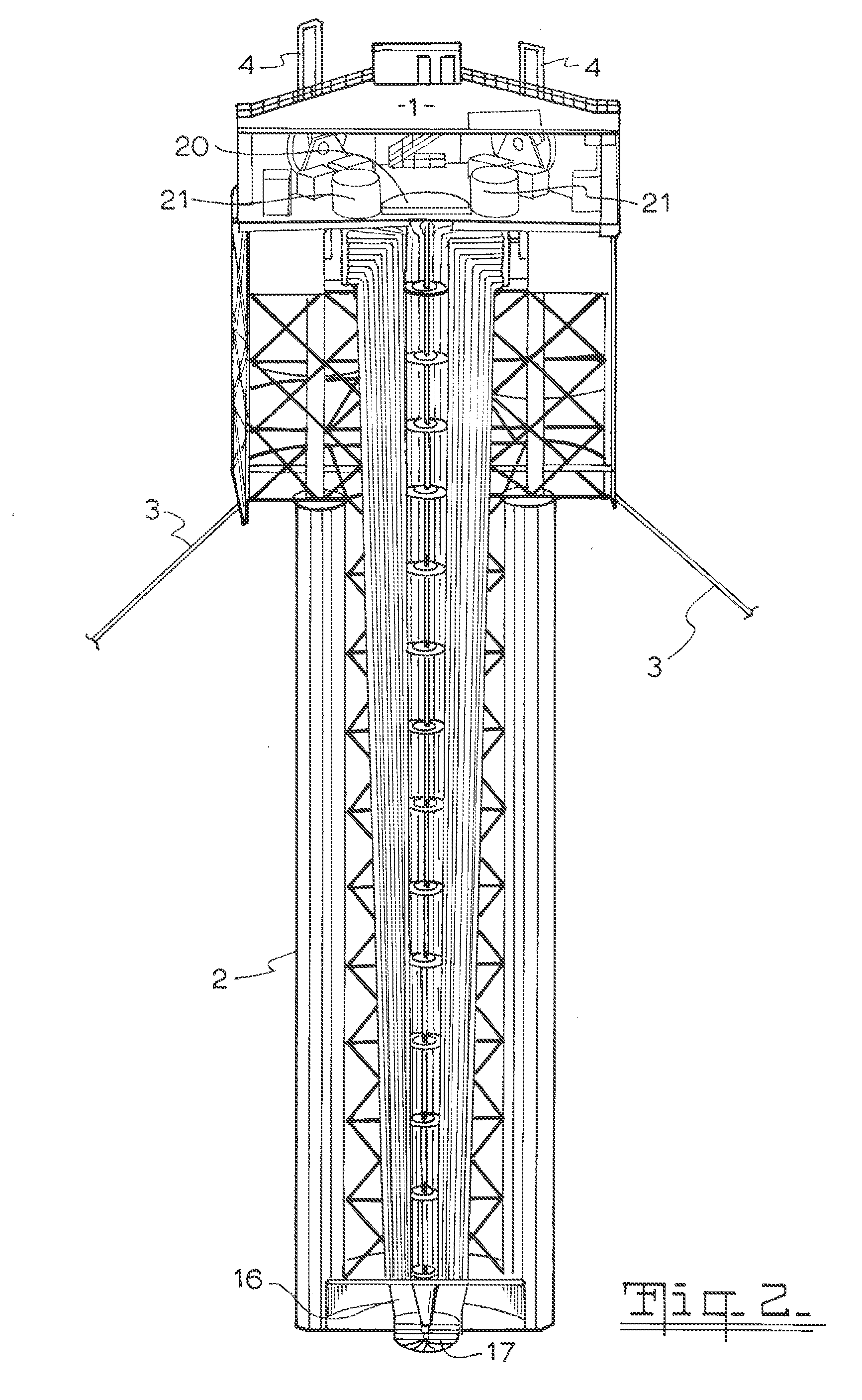
[0033]The installation of FIG. 1 comprises a platform 1 mounted on a vertical tower 2 and anchored to the sea bed by cables 3 so that tower 2 is maintained at a constant depth. Platform 1 is partially submerged so that buoyancy tanks 5 of wave energy collectors 4 move up and down with wave motion to drive air compressors 6.

[0034]Tanks 5 are ballasted with sea water and are partially submerged to optimize the collection of energy from swells of varying amplitude. For small waves there would only be a small amount of water inside tanks 5, approximately 1 meter, but for larger waves there would be approximately 3 to 4 meters of water to transfer the energy of tanks 5 falling to the compression and tension drives connecting to the flywheel of compressors 6. Sea current mills 7 comprise blades 8 which utilize sea current flows to drive air compressors 6 and current turbines 9 convert sea current flows into hydraulic power which is transferred through hydraulic lines to drive compressors ...


PUM


Abstract

A buoyancy hydro power installation comprises wave energy collectors and compressors mounted on a platform at sea level which sits on a vertical tower extending below sea level and houses compressed air pipes, expansion pipes, compressed air storage chambers and a turbine at the submerged end of the tower, said installation being tethered to the sea floor. The wave energy collectors comprise buoyancy tanks mounted on the platform which move up and down with wave motion which drives the air compressors and there are sea current energy collectors comprising turbines which are mounted on the outside of the vertical tower.

Description

CROSS-REFERENCE TO RELATED APPLICATION[0001]This application is a continuation-in-part of International Application No. PCT / AU2008 / 001084, filed 28 Jul. 2008.FIELD OF THE INVENTION[0002]This invention relates to the controlled generation of electricity from stored energy in response to power demand. The precursor source of energy can be excess off peak electrical power generation or renewable sources of energy such as sea waves and currents, wind or solar.BACKGROUND OF THE INVENTION[0003]There are now many installations which harness renewable energy. However the generation of power from renewable sources does not usually match the pattern of demand and there is a need to store energy and use it to generate electrical power with minimum losses during peak demand periods.[0004]There is also a need to store energy generated by conventional coal fired and nuclear power stations since even here it is difficult to match the generation of power with real time demand. One method of storage...

Claims


Application Information

Patent Timeline
IPC IPC(8): F03B13/18H02K7/18F03B13/00
CPCB63B1/048B63B35/44B63B2035/4466F03B13/187Y02E10/38F03B13/24F03B13/264F05B2240/93Y02E10/28F03B13/22Y02E10/30Y02E10/20
Inventor HARRIGAN, ALLAN KEITH
Owner BUOYANCY HYDRO
Why Eureka
Try Eureka