Solar wall tube

a solar wall and tube technology, applied in special doors/windows, doors/windows, building components, etc., can solve the problems of deep exterior recesses that collect rainwater, cover the unsightly space, and unfavorable use, so as to maximize the transmission of natural light

Active Publication Date: 2010-05-27
VITRABLOK
View PDF26 Cites 4 Cited by
  • Summary
  • Abstract
  • Description
  • Claims
  • Application Information

AI Technical Summary

Benefits of technology

[0010]In one embodiment of the present invention, an 8″×8″ or 8″×16″ four-sided stainless steel tube is enclosed at each end by one or two 8″×8″ glass blocks and sized to fit the glass blocks flush to interior and exterior wall surfaces. The stainless steel preferably has a mirror-like or otherwise reflective finish that maximizes the transmission of natural light and offers an aesthetic appearance that will endure. It also prevents any loading from above the opening being transferred to the glass block, thereby negating the necessity for lintels.
[0011]In one embodiment, a thermal break may be built into the stainless steel tube to reduce the loss of thermal energy, and a vent may be added to the tube to prevent moisture from building up inside. The enclosure may be wrapped with a durable moisture-resistant jacket that adheres to mortar, thereby further enhancing the cleanliness of the tube interior and long term resistance to debris or moisture. A weatherable UV-resistant sealant and liner securely holds the glass blocks in place for long term durability and pleasing aesthetic appearance. A vent in the bottom of the tube allows air circulation to prevent condensation.
[0012]Preferably, the tube is assembled with glass blocks protruding slightly from either end of the tube such that after installation the only material visible from the exterior surface is glass block and masonry. The enclosed tube with jacketing enables easy installation on a construction site without concerns of dirt or moisture getting into the tube interior during or after installation.

Problems solved by technology

On the one hand, putting a single (or multiple) glass block(s) unit flush with the exterior side or flush with the interior side or possibly somewhere in between, results in an unsightly deep hollow cavity on one or both sides of the block.
Also, in many cases, it results in a deep exterior recess that collects rainwater.
However, in addition to having to provide a small lintel over each glass block because it is non load-bearing, the designer now also must cover the resulting unsightly space (left after construction), between the blocks.
This area, if left unprotected or uncovered, could result in moisture and debris coming from the air space within the wall in the form of condensation and dirt buildup.
This is a practical solution for larger openings, but not as practical for small openings that would integrate into a masonry application where the desired opening would be, for example, 8″×8″ or 8″×16″.
Another approach might be to line the hard surfaces of the cavity to reduce the unsightly effect, but that would still leave the dark ragged air cavities visible from both the inside and outside of the building and would not solve the problems related to moisture and debris coming from the air space within the wall.
Such a liner would also be troublesome on a construction site with the installation of several pieces of material and sealants and additional opportunity to get moisture and debris in the visible space between the glass blocks.

Method used


Image

  • Solar wall tube
  • Solar wall tube
  • Solar wall tube

Examples


Embodiment Construction

[0027]It is to be understood that the figures and descriptions of the present invention have been simplified to illustrate elements that are relevant for a clear understanding of the invention. The detailed description will be provided hereinbelow with reference to the attached drawings.

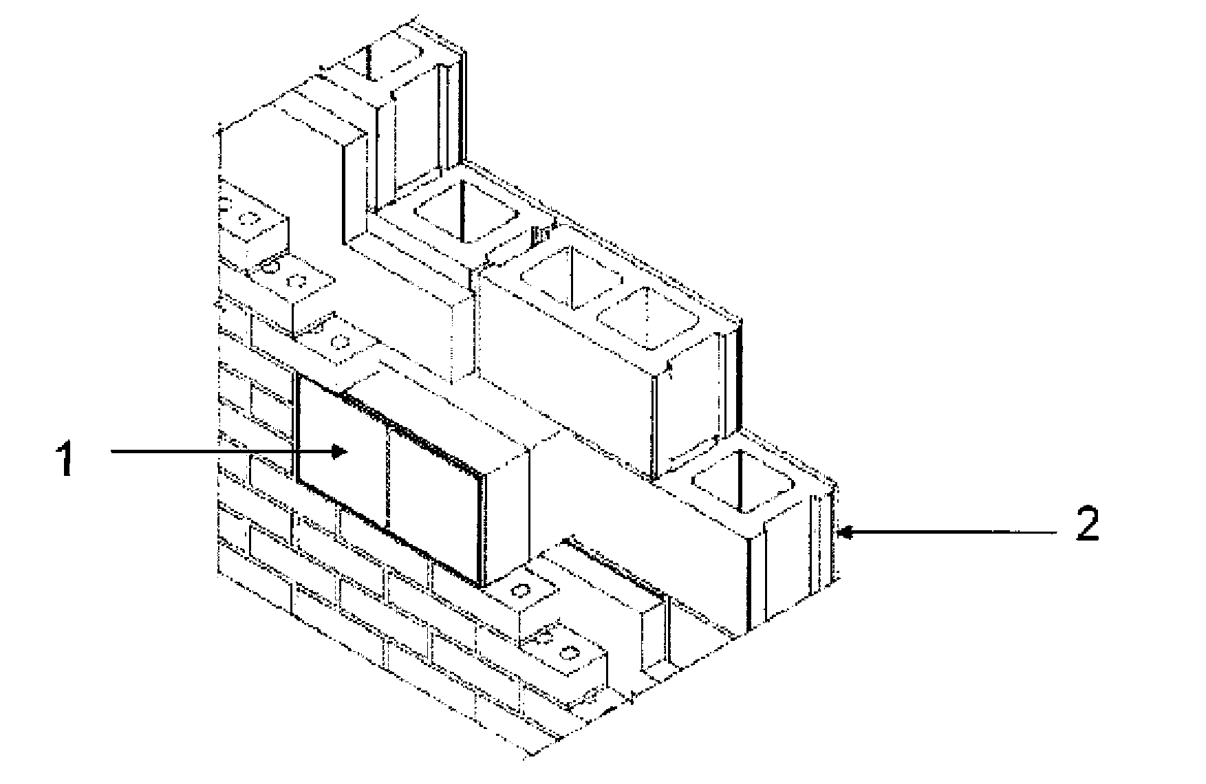
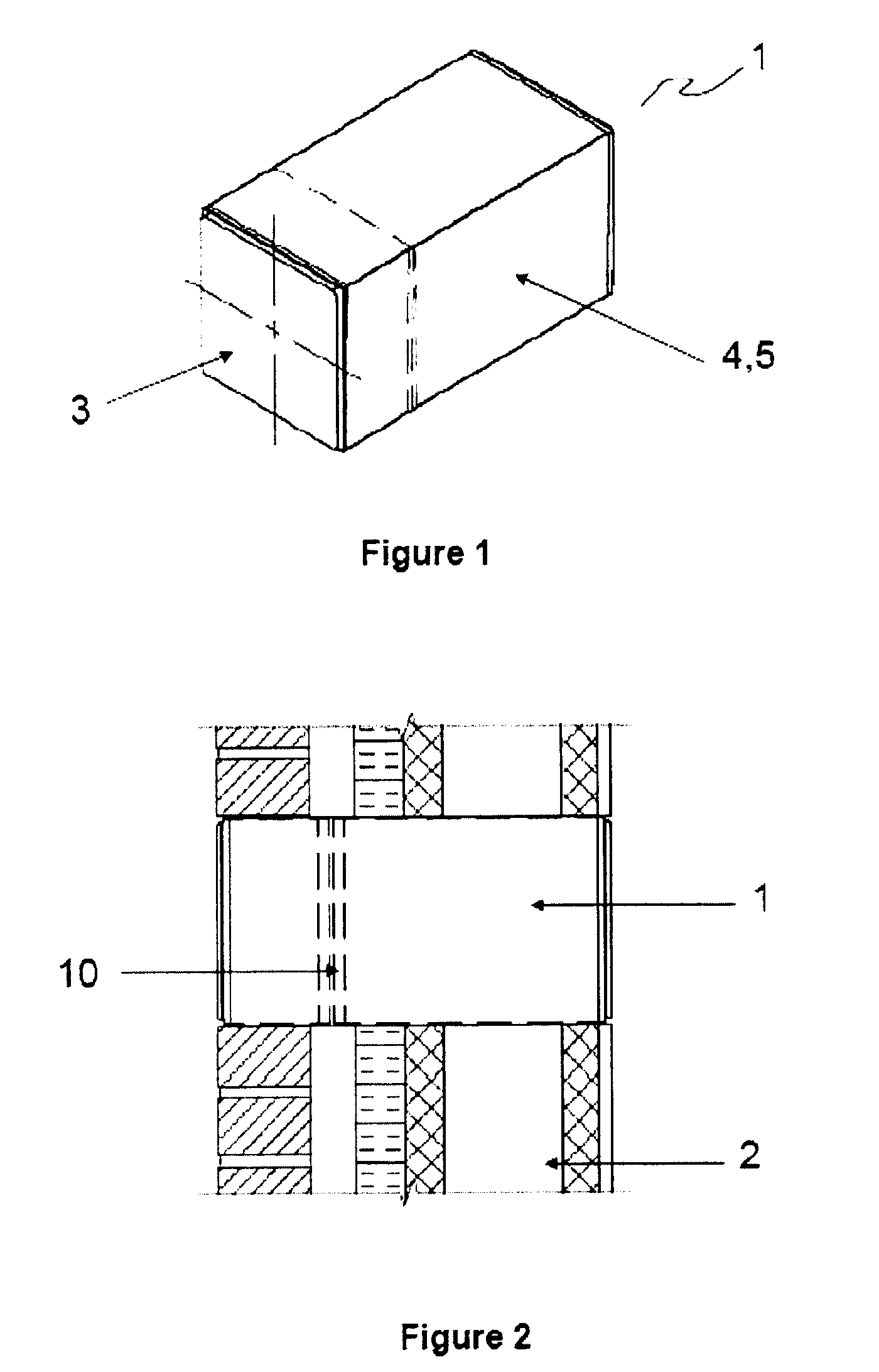
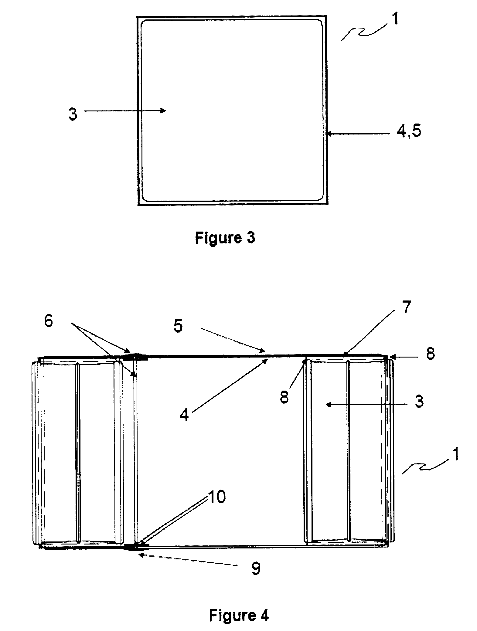
[0028]With reference to FIGS. 1-4, one embodiment of the completed Solar Wall Tube 1 preferably includes a multi-sided tube 4 that extends from the inside surface to the outside surface of a building and is enclosed at both ends with a glass block 3. To integrate into most masonry multi-wythe structures 2 the tube 4 may be rectangular, but it is logical to consider many alternatives such as a circular shaped tube 4 and glass block 3, or a tube 4 that is recessed on either the interior or exterior of a building to achieve a desired effect. While glass block is the preferred material for blocks to be used at the ends of the tube, blocks may also be made out resinous materials. Blocks may take the form ...


PUM


Abstract

A Solar Wall Tube, including a tube and one or more glass blocks, that integrates with masonry construction and guides natural light into a building is described. The tube structure provides a much cleaner aesthetic over previous glass block installation methods while guiding more natural light to the building interior. The Solar Wall Tube also offers advantages of significantly improved thermal insulation and structural integrity over a single glass block and longevity of an enclosed building material.

Description

PRIOR APPLICATIONS[0001]This application claims priority from U.S. Application No. 61 / 200,059, filed Nov. 24, 2008, entitled “The Solar Wall Tube”; U.S. Application No. 61 / 120,298, filed Dec. 5, 2008, entitled “The Solar Wall Tube”; and U.S. Application No. 61 / 163,787, filed Mar. 26, 2009, entitled “Solar Tube”.BACKGROUND OF THE INVENTION[0002]1. Field of the Invention[0003]The present invention relates to a solar wall tube that integrates with multi-wythe masonry and guides natural light into a building. The tube structure provides a cleaner aesthetic over previous glass block installation methods while guiding more natural light to the building interior. The tube also offers advantages of significantly improved thermal insulation over a single glass block and longevity of an enclosed building material.[0004]2. Background of the Invention[0005]Over the past several decades, architects have used glass blocks on exterior commercial walls as either an “architectural feature” integrate...

Claims


Application Information

Patent Timeline
Patent Type & Authority Applications(United States)
IPC IPC(8): E04C1/42E04C1/40
CPCE04C1/42
Inventor LOOMIS, NICHOLASATHERTON, PETER R.
Owner VITRABLOK
Why Eureka
Try Eureka