
Transmission network system

a network system and transmission network technology, applied in data switching networks, wavelength-division multiplex systems, multiplex communication, etc., can solve the problems of inability to eliminate, large time consumed by personal individual setting operations, and inability so as to prevent erroneous setting and significant curtailing labor costs

Inactive Publication Date: 2010-05-25
FUJITSU LTD
View PDF21 Cites 0 Cited by
  • Summary
  • Abstract
  • Description
  • Claims
  • Application Information

AI Technical Summary

Benefits of technology

The present invention is a transmission network system that allows for automatic setting of crosslinks between nodes. The system includes a transmission node and a receiving node, with a path setting receiving section, a path setting change section, and a change insertion section. The transmission node has a path setting receiving section for receiving information about changes in path settings, a path setting change section for changing the path settings, and a path-setting-receiving section for reporting the changes in path settings. The receiving node has a path setting receiving section for receiving the changes in path settings, a path setting change section for changing the path settings, and a path-setting-receiving section for reporting the changes in path settings. The system allows for the automatic setting of crosslinks between nodes, minimizing personal settings and preventing errors.

Problems solved by technology

Therefore, the operation becomes intricate, thereby raising a problem of a failure to eliminate erroneous setting.
Alternatively, considerable time must be consumed by personal individual setting operations.

Method used


Image

  • Transmission network system
  • Transmission network system
  • Transmission network system

Examples


Embodiment Construction

[0032]An embodiment of the present invention will be described hereinbelow by reference to the drawings.

[0033](a) Description of an embodiment of the present invention

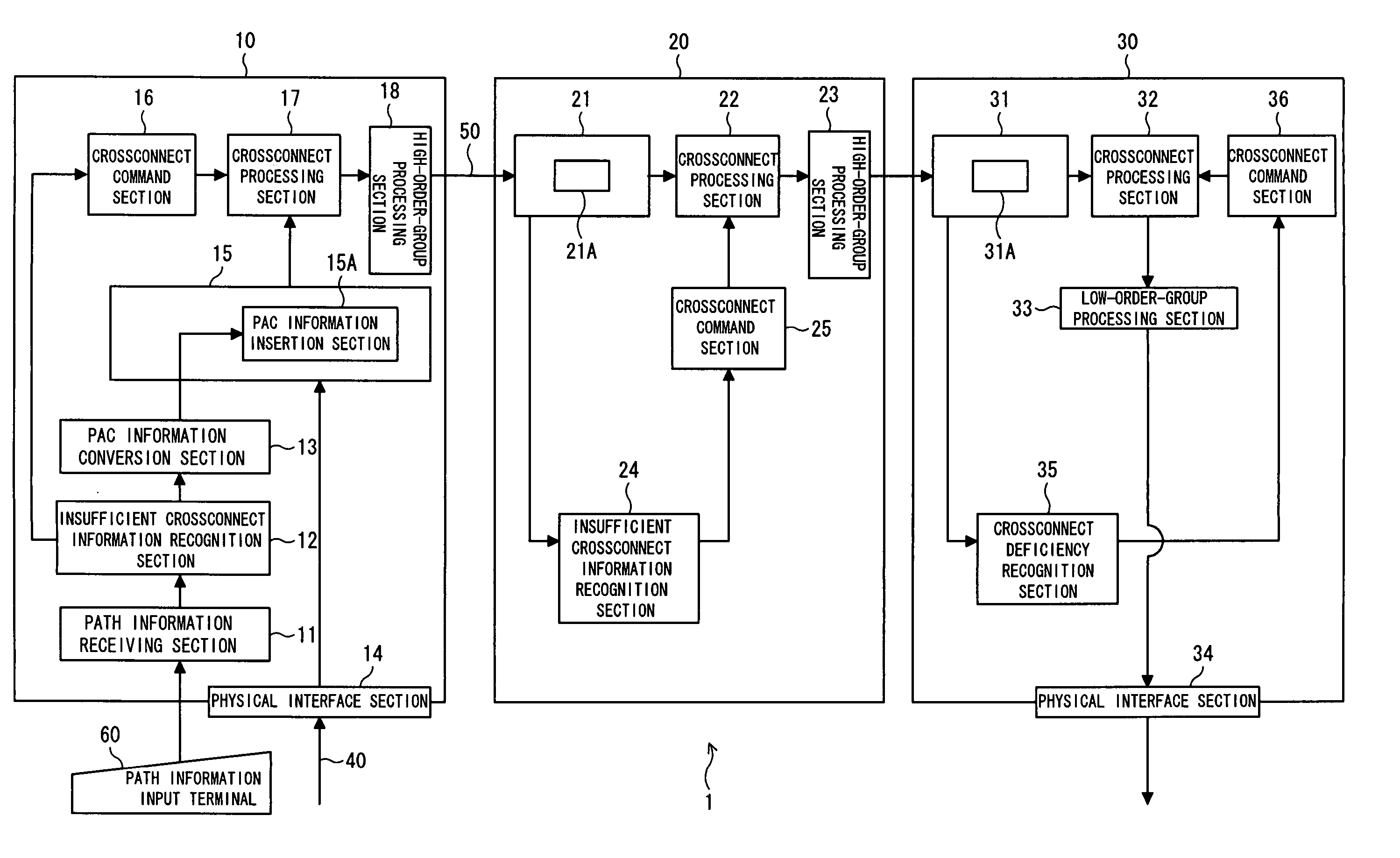
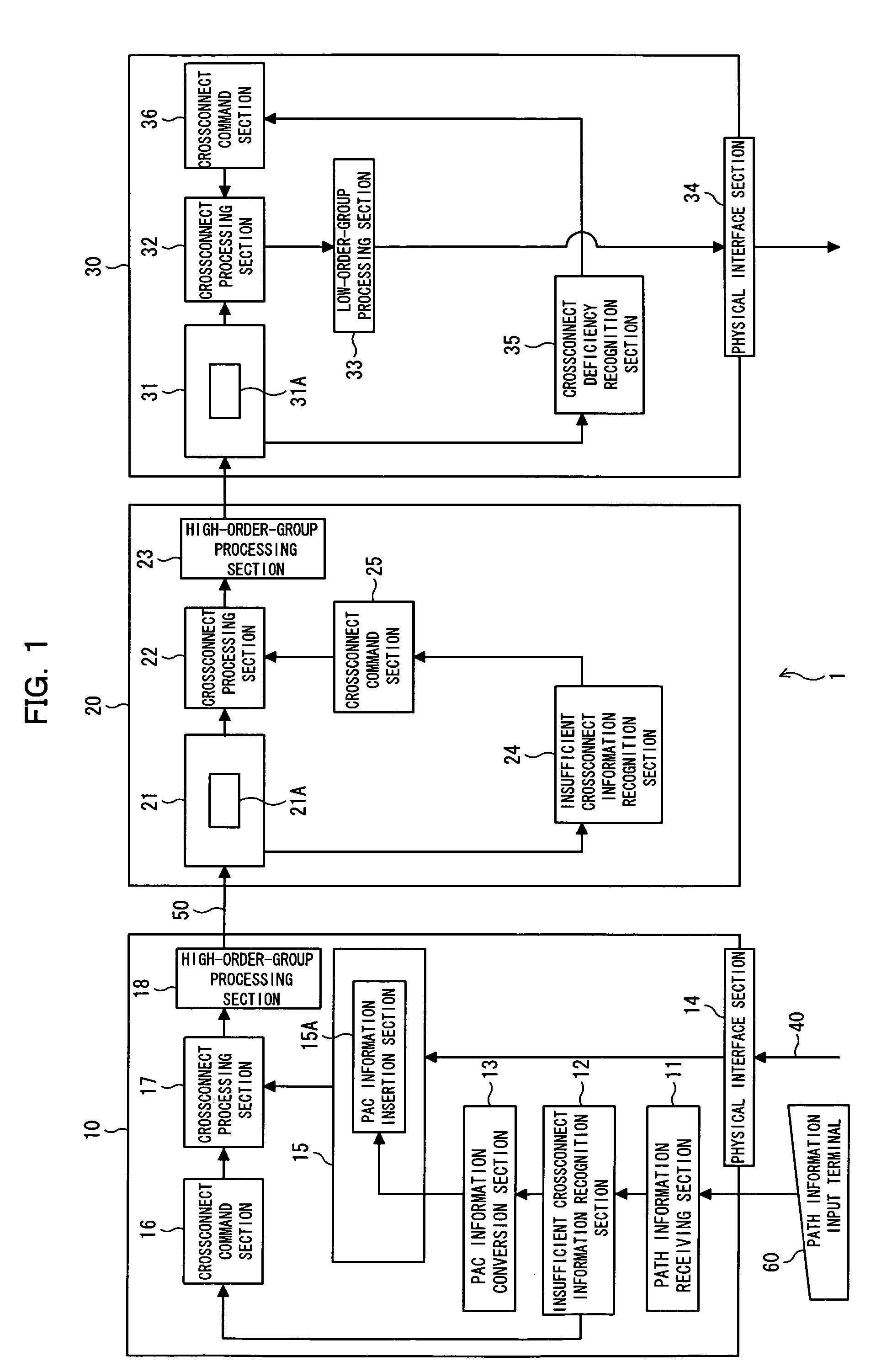
[0034]FIG. 1 is a block diagram showing an embodiment of the present invention. In FIG. 1, reference numeral 1 designates a transmission network system of the embodiment. In this transmission network system 1, a path [e.g., a VC-12 (Virtual Container 12) path] is set so as to pass through three nodes [also called NEs (Network Elements)]10, 20, and 30 constituting, e.g., a ring network serving as an SDH / SONET network. A transmission signal can be transmitted between the nodes 10 and 30.

[0035]In this transmission network system 1, when setting of the path between the nodes 10 and 30 is changed, information used for changing the path setting is inserted into header information about the transmission signal to be transmitted from the node 10 to the node 30 by way of the node 20, whereby the path setting can be autonomously...


PUM


Abstract

In a transmission network system in which a path is set between a transmission node and a receiving node and which transmits a transmission signal between the nodes, crossconnect settings of the nodes are enabled while personal settings are minimized.A transmission node has a first path-setting-receiving section; transmission-path-setting change sections; and change insertion sections which report information about a change in path setting received by said path-setting-receiving section by inserting the information into a transmission signal to be transmitted from the node to a receiving node. The receiving node has a second path-setting-receiving section and receiving-path-setting change sections for changing path settings of the node on the basis of the information about a change in path setting.

Description

[0001]This application is a continuation application, filed under 35 USC 111(a), of International Application PCT / JP2003 / 004897, filed Apr. 17, 2003.FIELD OF THE INVENTION[0002]The present invention relates to a transmission network system, and more particularly, to a transmission network system suitable for use with a synchronous network, such as an SDH (Synchronous Digital Hierarchy) or a SONET (Synchronous Optical Network).DESCRIPTION OF THE RELATED ART[0003]In an SDH / SONET transmission network, a path between nodes has hitherto been established by means of manually setting a crossconnect between individual transmission devices (nodes) constituting the network. Specifically, settings are made to link an AID (Access Identifier) serving as address information about a channel unit of a signal received by each node to AID information about a channel unit to which a signal is to be sent, through an operator's input operation performed by way of a personal computer or the like.[0004]Fo...

Claims


Application Information

Patent Timeline
Patent Type & Authority Patents(United States)
IPC IPC(8): H04Q11/00H04J3/00H04J3/12H04J3/16H04L12/28H04L12/70
CPCH04J3/12H04L49/357H04J3/1611H04J2203/0067H04J2203/0069H04J2203/006
Inventor KURASHIMA, KENJITOGO, TOSHIHIROWANG, ZHENHUA
Owner FUJITSU LTD
Learn More