Holographic Display

a holographic display and display technology, applied in the field of holographic displays, can solve the problems of limited view area, viewer discomfort, and large visible area, and achieve the effect of reducing the optical effect of lens aberration

Active Publication Date: 2010-06-24
SEEREAL TECHNOLOGIES
View PDF2 Cites 82 Cited by
  • Summary
  • Abstract
  • Description
  • Claims
  • Application Information

AI Technical Summary

Benefits of technology

[0053]The holographic display may be such that an optical effect of lens aberration can be reduced by correcting dynamically through encoding of the spatial light modulator.

Problems solved by technology

Here, a visibility region, which would typically be rather large, is limited to the locally positioned virtual observer windows.
One problem with autostereoscopically generated three dimensional images is that typically the viewer perceives the image to be inside the display, whereas the viewer's eyes tend to focus on the surface of the display.
This disparity between where the viewer's eyes focus and the perceived position of the three dimensional image leads to viewer discomfort after some time in many cases.

Method used


Image

  • Holographic Display
  • Holographic Display
  • Holographic Display

Examples


Embodiment Construction

A. Hologram Display with Calculation on the Same Substrate as the Pixels

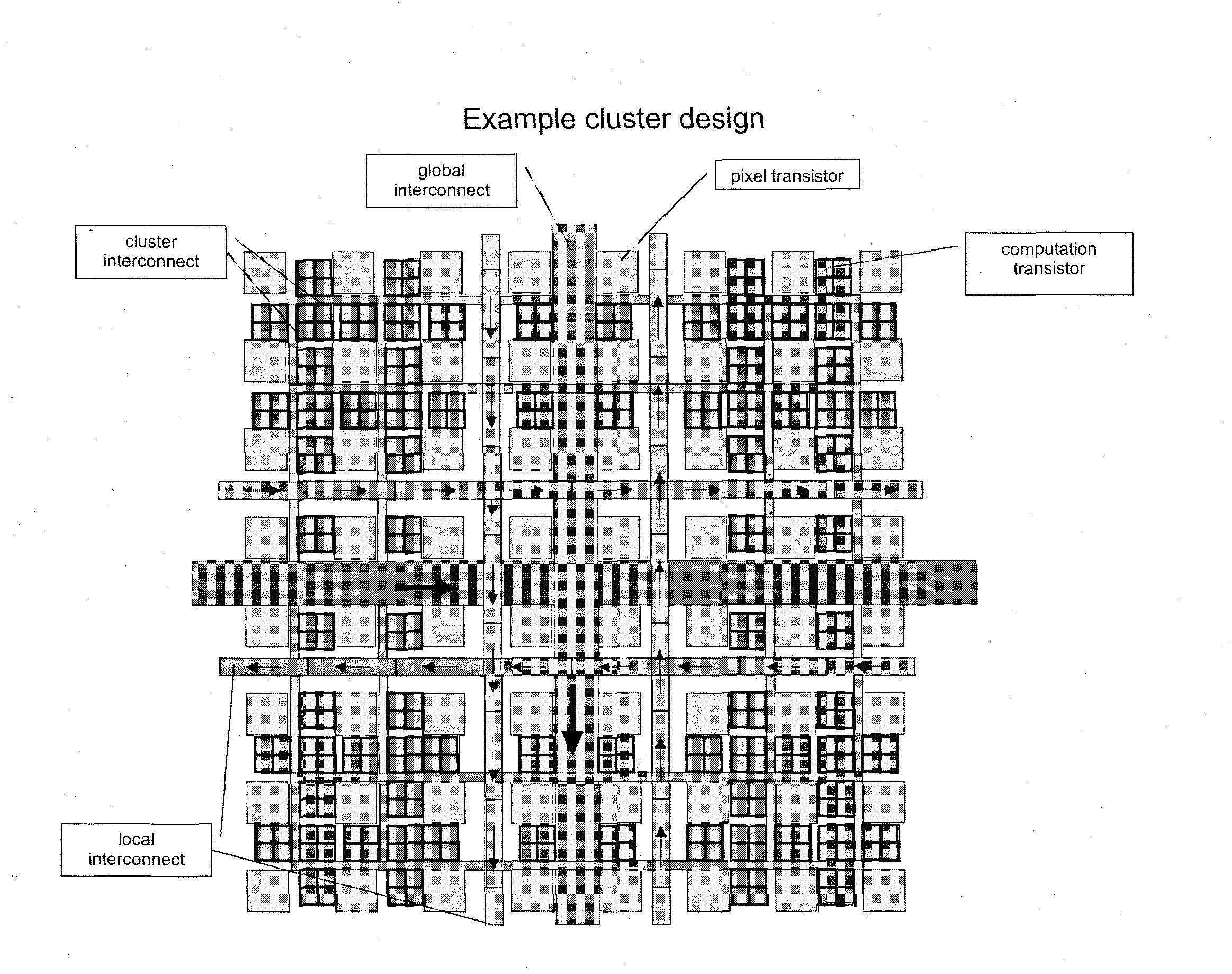
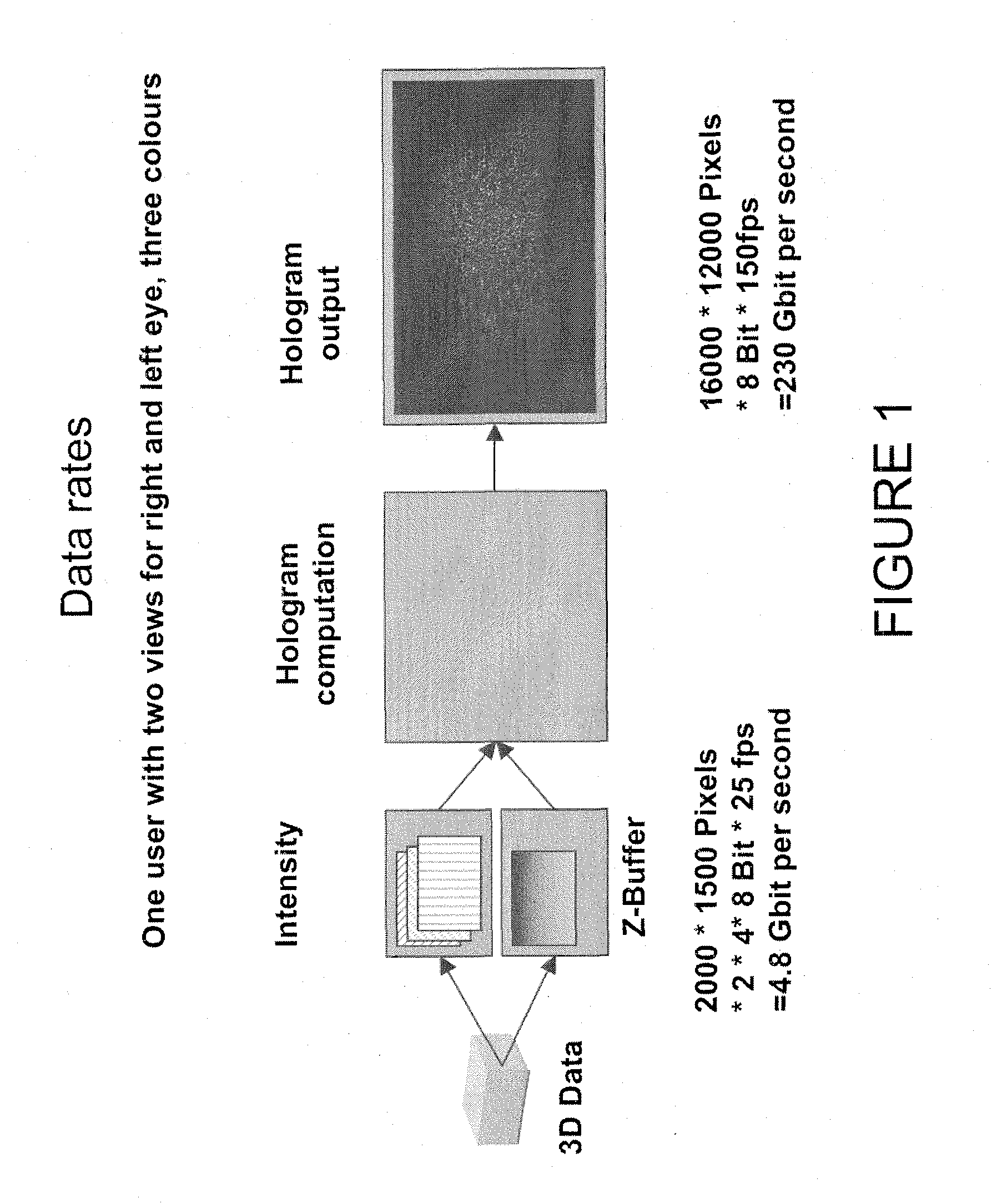
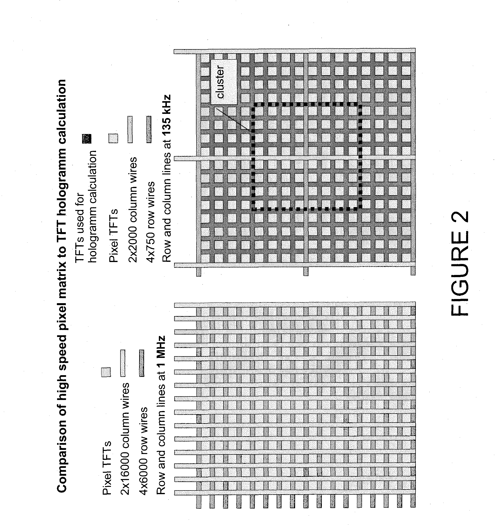
[0102]An implementation includes a display which receives real space image data, such as an intensity map and a depth map corresponding to a three dimensional image. The holographic encoding of the spatial light modulator is then calculated in real time or in quasi real time based on the three dimensional image data. At least some of the hologram calculations may be performed in the physical space in which the pixel matrix exists, by combining two functional units, namely the hologram calculation unit and the hologram display unit, which are separate functionally and spatially in prior art devices, so as to form a common unit which is implemented on one substrate. This means that transistors for at least some of the hologram calculation may be integrated between, or next to, the transistors used for pixel control. Alternatively, all the hologram calculations may be performed in the physical space in which the pi...


PUM


Abstract

Disclosed is a holographic display including a spatial light modulator, and including a position detection and tracking system, such that a viewer's eye positions are tracked, with variable beam deflection to the viewer's eye positions being performed using a microprism array which enables controllable deflection of optical beams.

Description

BACKGROUND OF THE INVENTION[0001]1. Field of the Invention[0002]The invention relates to a holographic display, especially to a holographic display on which computer-generated video holograms (CGHs) are encoded on a spatial light modulator. The holographic display may generate three dimensional holographic reconstructions.[0003]2. Technical Background[0004]Computer-generated video holograms (CGHs) are encoded in one or more spatial light modulators (SLMs); the SLMs may include electrically or optically controllable cells. The cells modulate the amplitude and / or phase of light by encoding hologram values corresponding to a video-hologram. The CGH may be calculated e.g. by coherent ray tracing, by simulating the interference between light reflected by the scene and a reference wave, or by Fourier or Fresnel transforms. An ideal SLM would be capable of representing arbitrary complex-valued numbers, i.e. of separately controlling the amplitude and the phase of an incoming light wave. Ho...

Claims


Application Information

Patent Timeline
Patent Type & Authority Applications(United States)
IPC IPC(8): G03H1/12G03H1/22
CPCG03H1/02G03H1/2205G03H2226/05G03H2223/18G03H2223/19G03H1/2294
Inventor KROLL, BOMISSBACH, ROBERTSCHWERDTNER, ALEXANDER
Owner SEEREAL TECHNOLOGIES
Why Eureka
Try Eureka