Image compressing apparatus, image compressing method, image decompressing apparatus, image decompressing method, image forming apparatus and recording meduim

a compression apparatus and compression method technology, applied in the field of image compression apparatus and an image compression, can solve the problems of large amount of process at the time of reception, small amount of process at the time of printing, image quality degradation, etc., and achieve the ratio of the first image for lossless compression and the lossless compression image. , the effect of high compression ra

Active Publication Date: 2010-12-30
SHARP KK
View PDF9 Cites 34 Cited by
  • Summary
  • Abstract
  • Description
  • Claims
  • Application Information

AI Technical Summary

Benefits of technology

[0033]The present invention has been made with the aim of solving the above problems, and it is an object of the invention to provide an image compressing apparatus and an image compressing method capable of efficiently performing compression process at a high compression rate while degradation in image quality is reduced by using lossy compression process and a plurality of different types of lossless compression process in combination, to provide an image decompressing apparatus and an image decompressing method capable of efficiently performing decompression process for the image compressed using the lossy compression process and the plurality of different types of lossless compression process, and to an image forming apparatus and a recording medium.
[0052]According to the present invention, compression process can be performed efficiently at a high compression rate by combing lossless compression process with lossy compression process and also by combing a plurality of different types of lossless compression process with each other. In particular, compression process can be performed efficiently for an image having numerous objects, such as a text (a character), a graphic (diagram) and a photograph, while the reproducibility of edges and the reusability of the image are maintained. Furthermore, decompression process can be performed efficiently for an image compressed using lossy compression process and a plurality of different types of lossless compression process.

Problems solved by technology

On the other hand, on storing image data in the format according to the final output image format, the amount of process at the time of the reception is large, but the amount of process at the time of printing is small.
Furthermore, when either format of image data is stored inside the printer 501 and reused after format conversion, image quality is degraded.
However, when the continuous tone image compressor 508 compresses the continuous tone bit map image data completely by performing lossless compression process, the rate of the compression is limited depending on the continuous tone bit map image data, and only a compression rate limited to some extent is obtained, although no difference occurs in image quality between before and after the image compression.
Since this type of apparatus reads the document optically, the digital image data contains noise and errors caused by a light source and a reading device.
Furthermore, since the optical resolution is limited, edges and the like cannot be reproduced, and the digital image data generated by the scanner function cannot reproduce the document completely.
Since the resolution of the visual sense of the human is high in low gray scales, blurs at edges caused by lossy compression are easily recognized as degradation in image quality.
Moreover, since photograph images, such as originally image-sensed images, represented using relatively large numbers of colors and gray scales have a large number of colors, when such images are subjected to lossless compression, the compression rates thereof are not expected to be improved.
However, the resolution of the visual sense of the human is low in multiple gray scales, and some differences in photograph images cannot be distinguished.
However, when a multifunctional printer segments an image into a photograph area suited for lossy compression based on the information written in PDL and performs lossy compression for the photograph area and performs lossless compression for the remaining image area into which text and vector images are segmented, there occurs a problem when image quality is balanced with compression rate.
On the other hand, if complicated lossless compression process is used, the amount of the process resources required for a constant throughput becomes relatively large, but the obtained compression rate can be made closer to the theoretical upper limit.
For the above-mentioned reasons, it is difficult to simultaneously attain a throughput higher than a constant level, a high image compression rate and a reduced amount of resources required for process while the wide value range of an input image is secured.

Method used


Image

  • Image compressing apparatus, image compressing method, image decompressing apparatus, image decompressing method, image forming apparatus and recording meduim
  • Image compressing apparatus, image compressing method, image decompressing apparatus, image decompressing method, image forming apparatus and recording meduim
  • Image compressing apparatus, image compressing method, image decompressing apparatus, image decompressing method, image forming apparatus and recording meduim

Examples


embodiment 1

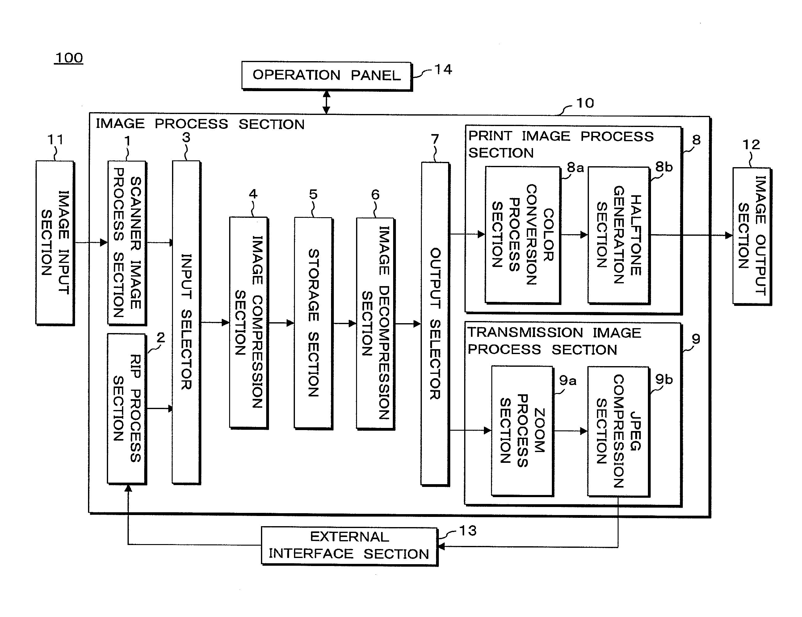
[0071]An image forming apparatus according to Embodiment 1 will be described below. FIG. 4 is a block diagram showing the configuration of an image forming apparatus 100 according to Embodiment 1. The image forming apparatus 100 (for example, a digital color multi-function peripheral) according to Embodiment 1 is equipped with an image input section 11, an image process section 10, an image output section 12, an external interface section 13, an operation panel 14, etc. The operations of these components provided for the image forming apparatus 100 are controlled by a CPU (central process unit), not shown.

[0072]The image forming apparatus 100 performs predetermined image process for image data obtained from the image input section 11 or the external interface section 13 using the image process section 10. Furthermore, the image forming apparatus 100 outputs (prints) images based on the processed image data using the image output section 12 or outputs the processed image data to an e...

embodiment 2

[0190]In the above-mentioned Embodiment 1, an area to be subjected to lossless compression in continuous tone bit map image data to be compressed is segmented into two areas (index image data for lossless compression and bit map image data for lossless compression) by the image compression section 4, and lossless compression methods different from each other are used for the two areas. Hence, the amount of resources required for each type of process can be balanced with the improvement in compression rate in each type of process.

[0191]In addition to the above-mentioned configuration, it may be possible to have a configuration in which an area to be subjected to lossless compression in continuous tone bit map image data is broken down more finely, for example, the area to be subjected to lossless compression is segmented into three kinds of image data based on the frequency of occurrence of colors to be used. In this case, for example, as a first segmentation image, pixels having thr...

embodiment 3

[0199]In Embodiments 1 and 2 Described Above, a Configuration is described in which the image compressing apparatus and the image decompressing apparatus according to the present invention are mounted in the same image forming apparatus 100. In Embodiment 3, a configuration is described in which the image compressing apparatus according to the present invention is mounted in a PC and the image decompressing apparatus according to the present invention is mounted in the image forming apparatus.

[0200]FIG. 15 is a block diagram showing the configuration of the main section of a PC according to Embodiment 3. A PC 200 according to Embodiment 3 is equipped with a PDL data generation section 201, an RIP process section202, an image compression section 203, a storage section 204, an external interface section 205, etc. The RIP process section 202, the image compression section 203, the storage section 204 and the external interface section 205 provided for the PC 200 according to Embodiment...


PUM


Abstract

When compressing continuous tone bit map image data, the image compression section of the image compressing apparatus segments the continuous tone bit map image data into bit map image data for lossy compression, index image data for lossless compression and bit map image data for lossless compression based on pixel identification information data. The lossy compression section of the image compression section performs lossy compression process according to the JPEG method for the bit map image data for lossy compression, and the first lossless compression section thereof performs lossless compression process according to the JBIG method for the index image data for lossless compression. Furthermore, the second lossless compression section thereof performs lossless compression process according to the JPEG-LS method for the bit map image data for lossless compression.

Description

CROSS-REFERENCE TO RELATED APPLICATIONS[0001]This Nonprovisional application claims priority under 35 U.S.C. §119(a) on Patent Application No. 2009-151206 filed in Japan on Jun. 25.2009, the entire contents of which are hereby incorporated by reference.BACKGROUND[0002]1. Technical Field[0003]The present invention relates to an image compressing apparatus and an image compressing method for compressing an image, an image decompressing apparatus and an image decompressing method for decompressing a compressed image, an image forming apparatus, and a recording medium.[0004]2. Description of Related Art[0005]Apparatuses having a printing function, such as those referred to as a monofunctional printer or a multifunctional printer, have been widely used. Such a printing apparatus generally receives image information for forming an output image from an external personal computer (hereafter referred to as a PC) or the like via a wired or wireless communication path, forms an output image by...

Claims


Application Information

Patent Timeline
Patent Type & Authority Applications(United States)
IPC IPC(8): G06K9/34G06K9/36H04N1/413
CPCH04N1/00278H04N1/413H04N19/103H04N19/17H04N19/136H04N19/186H04N19/12
Inventor YOSHIMURA, HIDEYOSHI
Owner SHARP KK
Why Eureka
Try Eureka