Method and system for identifying a potential lead failure in an implantable medical device

a medical device and potential failure technology, applied in continuity testing, therapy, instruments, etc., can solve problems such as failure of electrodes failure of electrodes,

Active Publication Date: 2011-01-13
PACESETTER INC
View PDF12 Cites 19 Cited by
  • Summary
  • Abstract
  • Description
  • Claims
  • Application Information

AI Technical Summary

Benefits of technology

[0010]In another embodiment, an implantable medical device is provided. The device includes a lead, a channel selection module and a failure detection module. The lead includes electrodes configured to be positioned within a heart and capable of sensing cardiac signals to determine a first signal over a first channel between a first combination of the electrodes and a second signal over a second channel between a second combination of the electrodes. The channel selection module is configured to control which of the electrodes are included in the first and second combinations of electrodes. The failure detection module determines whether at least one of the first and second signals is representative of a...

Problems solved by technology

A lead failure occurs when an electrode fails.
The electrodes may fail and no longer be capable of accurately sensing and communicating cardiac signals to the IMD.
Known lead failures involve electrodes fracturing, breaking or becoming dislodged from the myocardium.
Lead failures can result in increased noise in the cardiac signals communicated to the IMD.
With respect to fractured electrodes, the noise may be caused by the fractured components of the electrode rapidly making and breaking contact with one another at the fracture site.
Lead failures can result in an IMD applying unnecessary or incorrect pacing or stimulation pulses to the heart.
The IMD may then erroneously ap...

Method used


Image

  • Method and system for identifying a potential lead failure in an implantable medical device
  • Method and system for identifying a potential lead failure in an implantable medical device
  • Method and system for identifying a potential lead failure in an implantable medical device

Examples


Embodiment Construction

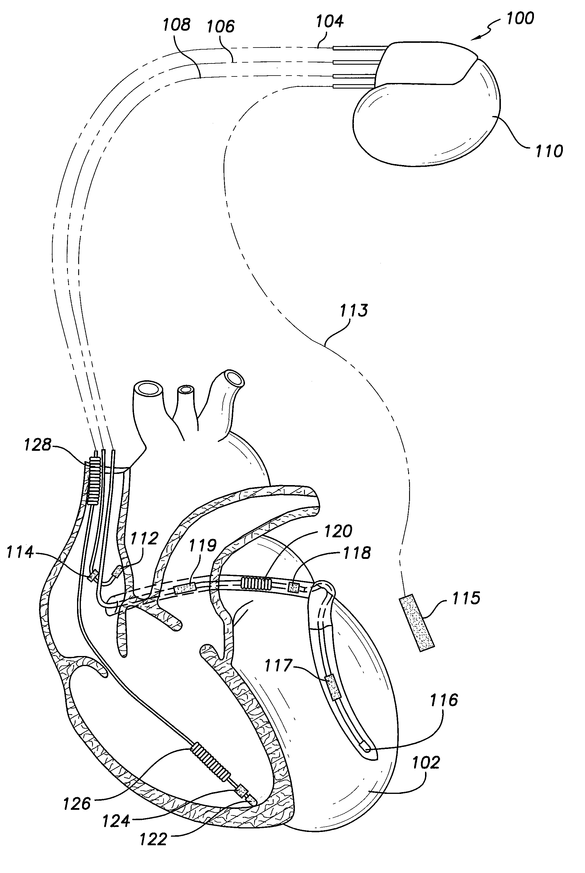
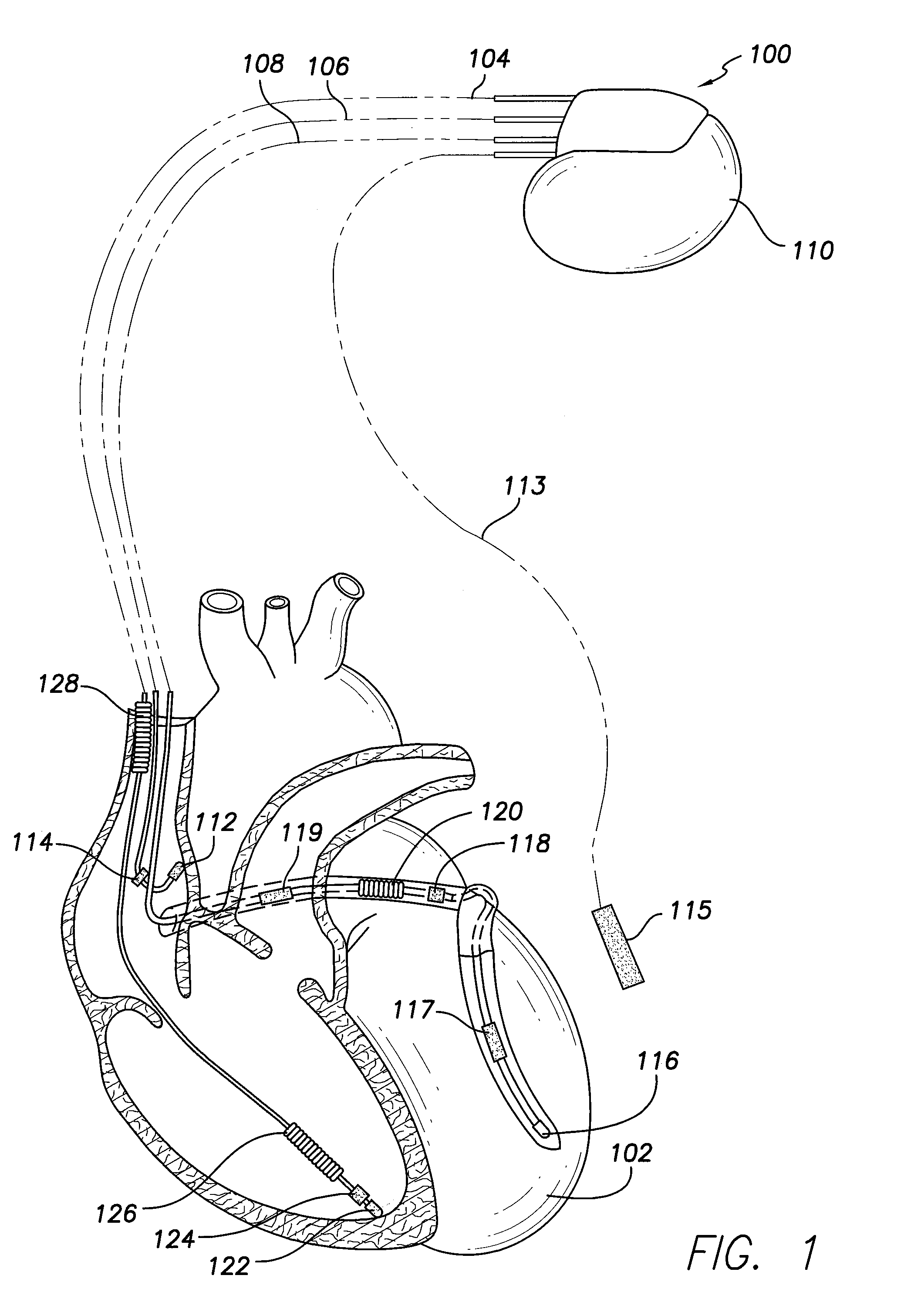
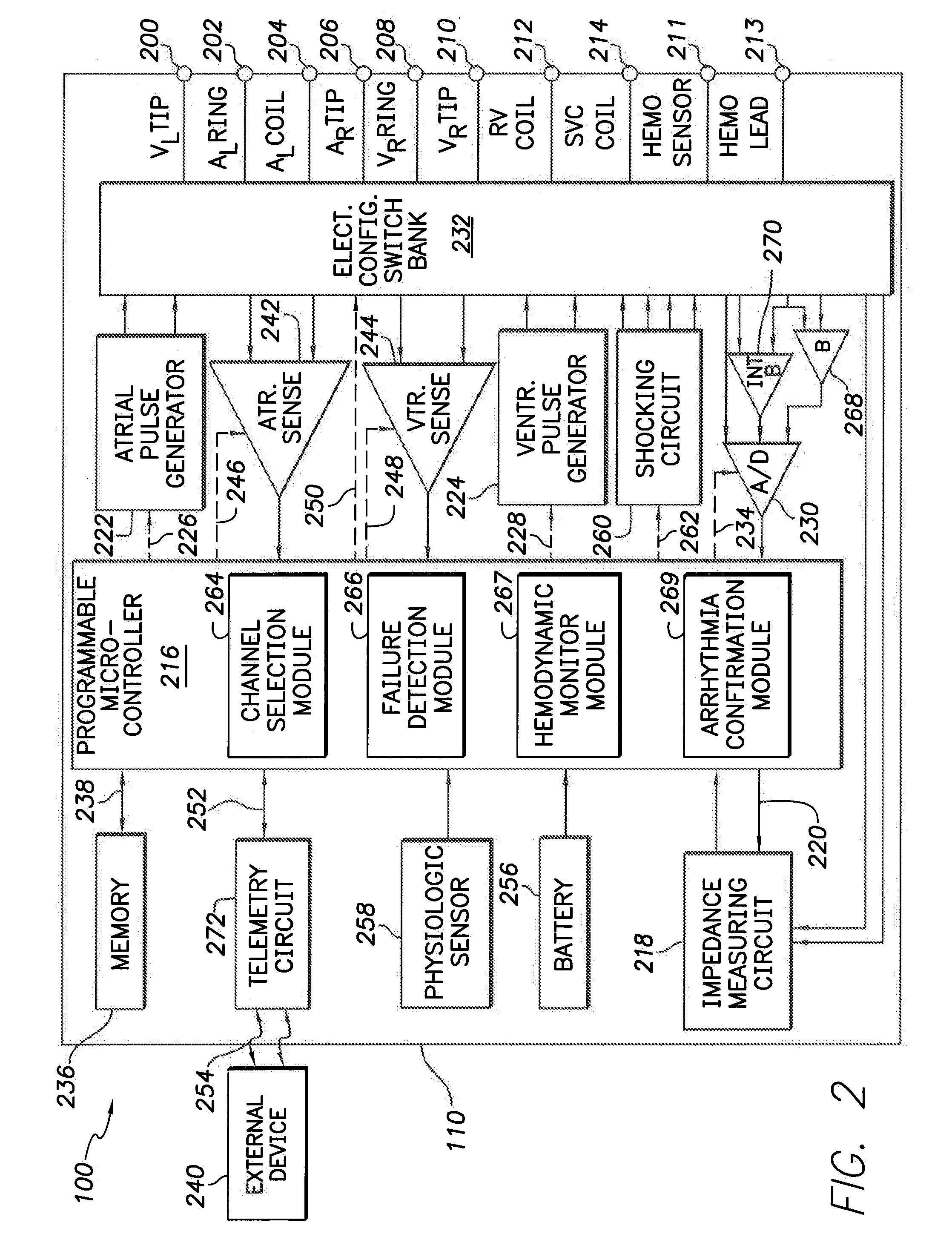
[0020]In the following detailed description, reference is made to the accompanying drawings which form a part hereof, and in which are shown by way of illustration specific embodiments in which the present invention may be practiced. These embodiments, which are also referred to herein as “examples,” are described in sufficient detail to enable those skilled in the art to practice the invention. It is to be understood that the embodiments may be combined or that other embodiments may be utilized, and that structural, logical, and electrical variations may be made without departing from the scope of the present invention. The following detailed description is, therefore, not to be taken in a limiting sense, and the scope of the present invention is defined by the appended claims and their equivalents. In this document, the terms “a” or “an” are used, as is common in patent documents, to include one or more than one. In this document, the term “or” is used to refer to a nonexclusive o...


PUM


Abstract

A method for detecting potential failures by a lead of an implantable medical device is provided. The method includes sensing a first signal over a first channel between a first combination of electrodes on the lead and sensing a second signal from a second channel between a second combination of electrodes on the lead. The method determines whether at least one of the first and second signals is representative of a potential failure in the lead and identifies a failure and the electrode associated with the failure based on which of the first and second sensed signals is representative of the potential failure. Optionally, when the first and second sensed signals are both representative of the potential failure, the method further includes determining whether the first and second sensed signals are correlated with one another. When the first and second sensed signals are correlated, the method declares an electrode common to both of the first and second combinations to be associated with the failure.

Description

FIELD OF THE INVENTION[0001]Embodiments of the present invention generally pertain to implantable medical devices and more particularly to methods and systems that identify potential lead failures in the devices and take corrective action based thereon.BACKGROUND OF THE INVENTION[0002]An implantable medical device (IMD) is implanted in a patient to monitor, among other things, electrical activity of a heart and to deliver appropriate electrical therapy, as required. Implantable medical devices include pacemakers, cardioverters, defibrillators, implantable cardioverter defibrillators (ICD), and the like. The electrical therapy produced by an IMD may include pacing pulses, cardioverting pulses, and / or defibrillator pulses to reverse arrhythmias (e.g., tachycardias and bradycardias) or to stimulate the contraction of cardiac tissue (e.g., cardiac pacing) to return the heart to its normal sinus rhythm.[0003]Electrodes coupled to leads are implanted in the heart to sense the electrical a...

Claims


Application Information

Patent Timeline
IPC IPC(8): A61N1/37
CPCA61N2001/083G01R31/026A61N1/3706A61N1/371A61N1/37G01R31/54
Inventor BORNZIN, GENE A.POORE, JOHN W.WILLIAMSON, RICHARDMOUCHAWAR, GABRIEL A.FAIN, ERIC S.
Owner PACESETTER INC
Why Eureka
Try Eureka