Filter

Inactive Publication Date: 2011-01-27
DYSON TECH LTD
View PDF81 Cites 14 Cited by
  • Summary
  • Abstract
  • Description
  • Claims
  • Application Information

AI Technical Summary

Benefits of technology

[0016]Such an arrangement may be advantageous because, during use, the upstream end of the filter medium will be exposed to the most dust and a larger pore size will be better able to accommodate this dust without restricting airflow through the filter medium. Further downstream, smaller pore sizes will trap any smaller dust particles which have passed through the upstream portion of the filter. This arrangement may advantageously help to lower the pressure loss across the electrostatic filter.
[0035]Preferably the corona discharge electrode, and / or the electrode of low curvature may project upstream from an upstream surface of the filter medium. Ideally the discharge electrode and / or the electrode of low curvature may project below a lower surface or above an upper surface of the filter medium. In a particular embodiment the electrode of low curvature projects both upstream and downstream from a lower surface of the corona discharge electrode. This is advantageous because it helps to maximize the volume over which the ionizing field is generated to maximize the opportunity for charging dust particles as they pass through the ionizing field.

Problems solved by technology

Such electrostatic filters are relatively cheap to produce but suffer from the disadvantage that their charge dissipates over time resulting in a reduction of their electrostatic properties.
This in turn reduces the amount of dust the electrostatic filter can collect which may shorten the life of both the electrostatic filter itself and any further downstream filters.
A disadvantage with this arrangement is that they are relatively inefficient, are made from relatively expensive materials and the collector electrodes require constant maintenance in order to keep them free of collected dust.
Once the collector electrodes are coated in a layer of dust they are much less efficient.
While this arrangement is compact it suffers from the disadvantage that dust collects on the inside of the cyclones.
Not only does this require constant and difficult maintenance removing dust from the walls of the cyclone, but also any dust trapped inside the cyclone will interfere with the cyclonic airflow decreasing the separation efficiency of the cyclone itself.

Method used


Image

  • Filter
  • Filter
  • Filter

Examples


Embodiment Construction

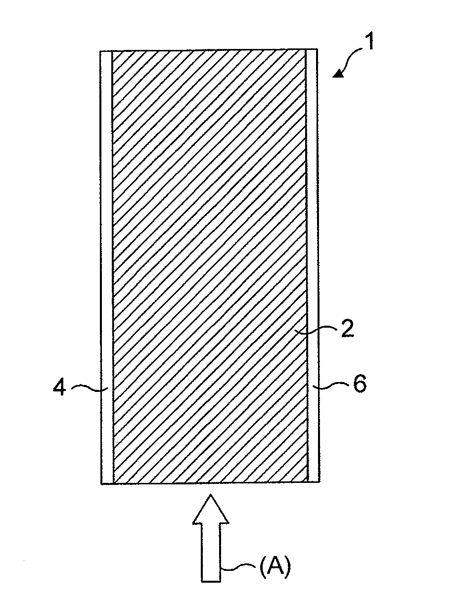
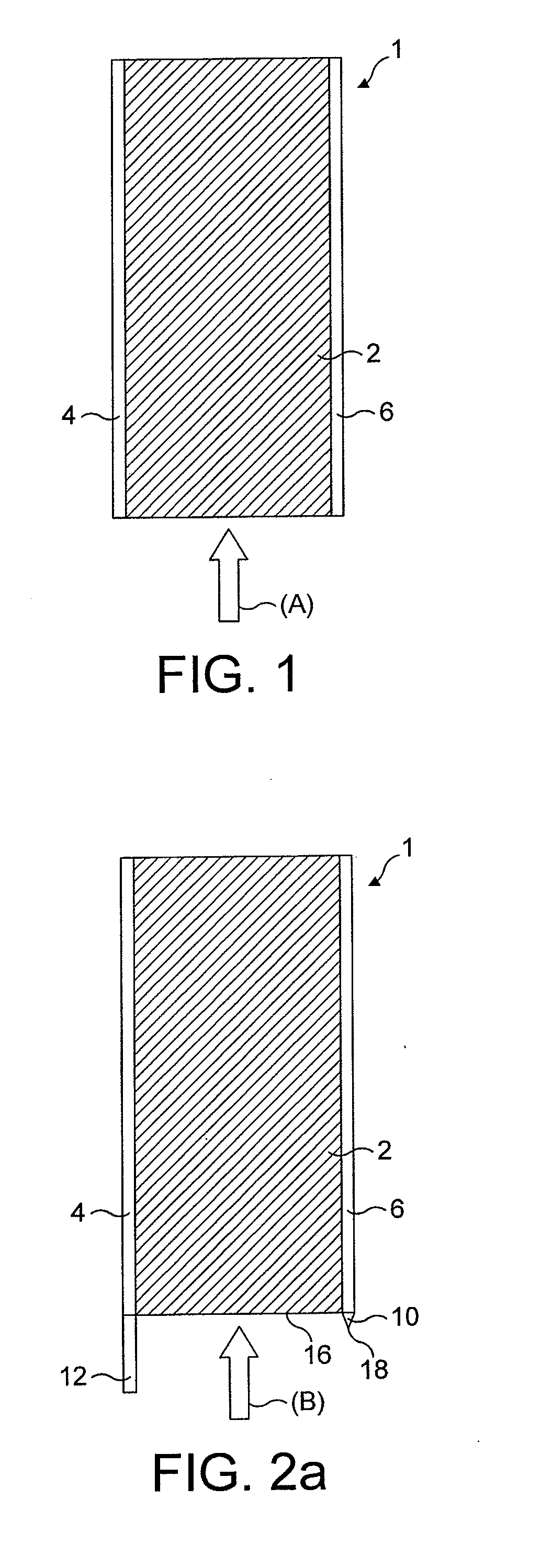
[0069]With reference to FIG. 1 an electrostatic filter is shown and indicated generally by the reference numeral 1.

[0070]It can be seen that the electrostatic filter 1 comprises an electrically resistive filter medium 2 sandwiched between and in contact with a first non-porous electrode 4 and a second non-porous electrode 6. In use the first and second electrodes 4, 6 are each at a different voltage such that a potential difference is formed across the electrically resistive filter medium 2. The first electrode 4 is at 0 Volts and the second electrode 6 is at + / −4 to 10 kV during use. The electrodes 4, 6 are connected to a high voltage power supply (not shown).

[0071]The first and second electrodes 4, 6 form at least part of an air pathway which is filled by the electrically resistive filter medium 2 such that in use dust laden air (A) must pass through the electrically resistive filter medium 2 along the length of the first and second electrodes 4,6. The potential difference generat...


PUM

PropertyMeasurementUnit
Thicknessaaaaaaaaaa
Thicknessaaaaaaaaaa
Lengthaaaaaaaaaa

Abstract

The present invention relates to an electrostatic filter. Particularly but not exclusively the invention relates to an electrostatic filter for removing dust particles, for example an electrostatic filter for use in a vacuum cleaner, fan or air conditioner. The electrostatic filter includes a filter medium located between a first and a second electrode, each at a different voltage during use, such that a potential difference is formed across the filter medium, wherein a property of the filter medium varies along the length of the filter medium.

Description

REFERENCE TO RELATED APPLICATION[0001]This application claims the priority of United Kingdom Application No. 0912936.2, filed Jul. 24, 2009, the entire contents of which are incorporated herein by reference.FIELD OF THE INVENTION[0002]The present invention relates to an electrostatic filter. Particularly, but not exclusively the invention relates to an electrostatic filter for removing dust particles from an airstream, for example an electrostatic filter for use in a vacuum cleaner, fan or air conditioner.BACKGROUND OF THE INVENTION[0003]It is well known to separate particles, such as dirt and dust particles from a fluid flow using mechanical filters, such as foam filters, cyclonic separators and electrostatic separators where dust particles are charged and then attracted to another oppositely charged surface for collection.[0004]Known cyclonic separating apparatus include those used in vacuum cleaners. Such cyclonic separating apparatus are known to comprise a low efficiency cyclon...

Claims


Application Information

Patent Timeline
IPC IPC(8): A47L9/10B03C3/00B03C3/34
CPCA47L9/10A47L9/12B03C3/30B03C3/025B03C3/155B03C3/017B03C3/41B03C3/15B01D35/06B01D46/42B01D46/50
Inventor HORNE, LUCAS
Owner DYSON TECH LTD
Why Eureka
Try Eureka