
Method for preparing an ion exchange media

a technology of ion exchange media and composite ion exchange media, which is applied in the direction of water/sewage treatment by ion exchange, refrigeration components, electrodialysis, etc., can solve the problems of deteriorating quality that needs flow reduction, insatisfactory flux, and limited thickness, so as to prevent any undesirable water splitting and reduce power consumption

Active Publication Date: 2007-05-10
AQUATECH INT LLC
View PDF20 Cites 0 Cited by
  • Summary
  • Abstract
  • Description
  • Claims
  • Application Information

AI Technical Summary

Benefits of technology

"The patent describes a new design for ion exchange media used in electro de-ionization processes. The media is made up of two parts: a porous part and a transport framework. The porous part allows water to flow through it and has a high number of bipolar sites for efficient ion transport. The transport framework helps to transfer ions to the concentrate compartment while maintaining their quality. The media is designed to have maximum flow and minimum resistance to the flow path, and it is in direct contact with the membrane surface to eliminate any channeling of water. The media is also made to have a fine surface to ensure complete contact with the membrane and to minimize power consumption. The technical effects of this design include improved quality of de-ionized water, increased efficiency of ion transport, and reduced power consumption."

Problems solved by technology

However, by doing this there is a limitation in terms of the thickness because of the ability of the system to transfer ions to the concentrate compartment.
This can be quickly seen in terms of deteriorating quality that needs flow to be reduced to maintain quality.
At the same time, if the media is made of finer resin particles the ion transportation is significantly improved evidenced by the time taken to get a desirable quality but the flux achieved is not satisfactory.

Method used


Image

  • Method for preparing an ion exchange media
  • Method for preparing an ion exchange media
  • Method for preparing an ion exchange media

Examples


examples

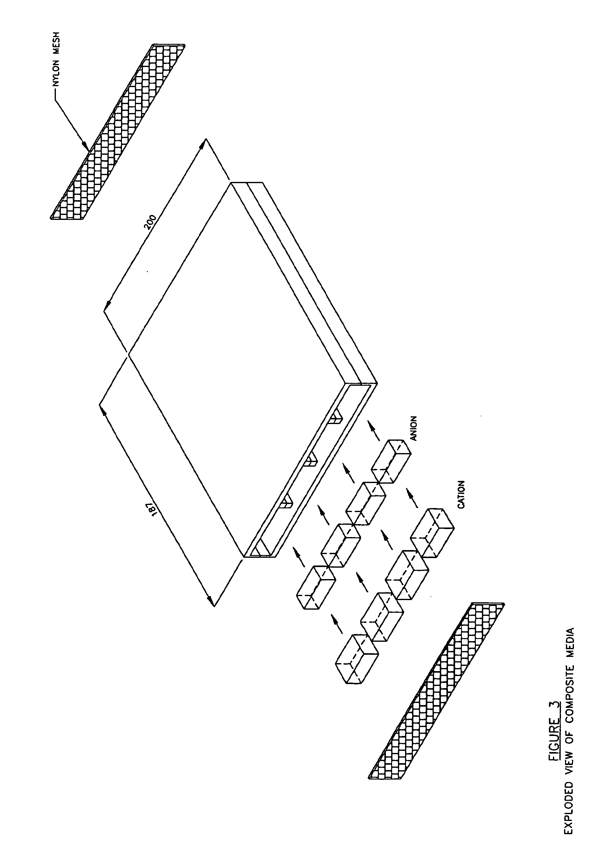
[0048] The examples detailed here explain preparation of Flow path domains, blocks or tablets and Transport framework along with flow dividers. These components have been assembled together into a dilute compartment and several of these have been used to create an electro deionization assembly. Various experiments have been carried out and experimental data has been plotted in graphs.

[0049] Method of preparation of media and details of various experiments are as follows:

experiment 1

Preparation of the Framework and Tablets

[0050] One set of die is made of the size 200×187 mm of different thickness as required for the selected size of the dilute compartment. The media was made here for dilute compartment thickness of 11.3 mm.

[0051] Anion resin in Cl form and cation in Na form resin separately dried through air or vacuum dried to reduce moisture content between 10 to 20%.

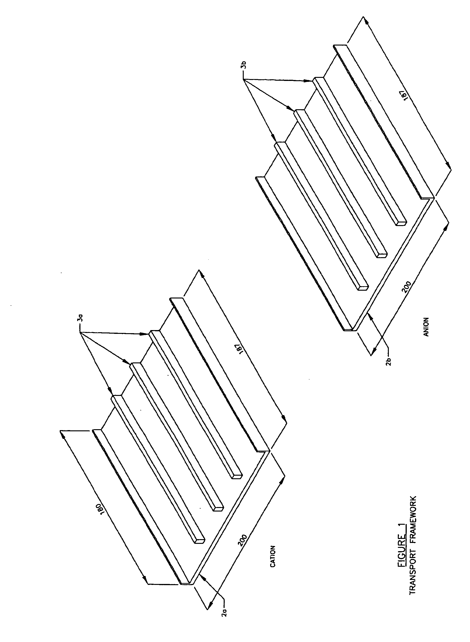
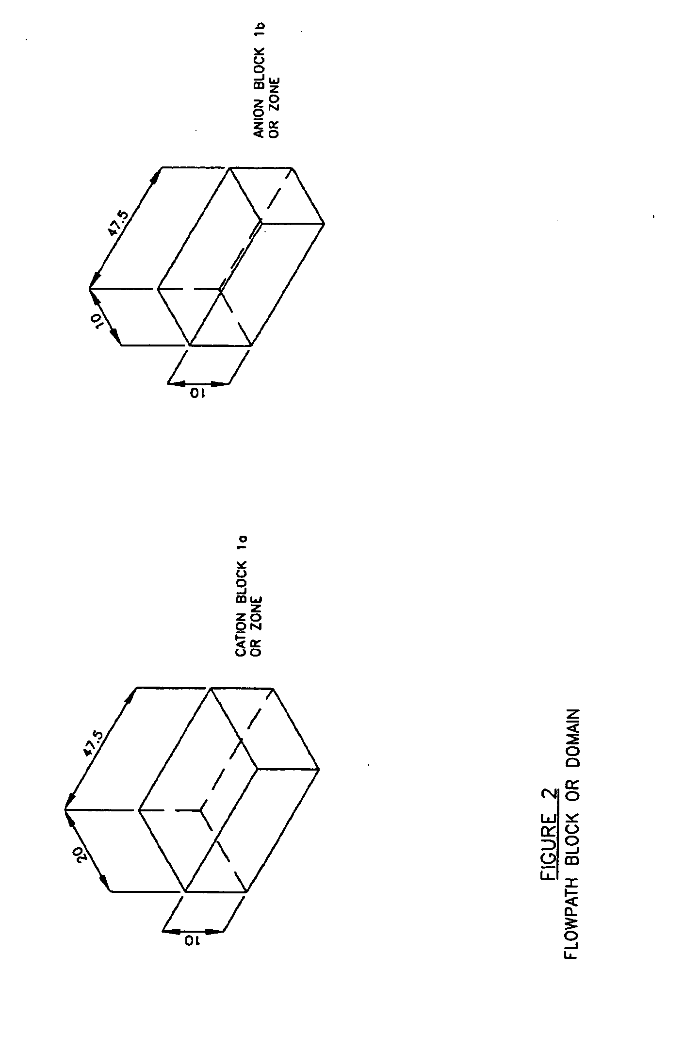
[0052] As shown in FIG. 1, separate anion resin bed was made by 127 grams on 100% dry basis and blended with suitable binding agent in the range of 1% to 10% (preferably 5 to 7%). The dough was prepared filled in the die and pressed on drying. Similarly separate cation resin bed was by 169 gms of material on 100% dry basis with suitable binding agent in the range of 0.5 to 5%, (preferably between 3 to 5%). The ratio of anion and cation in one bed was kept in ratio of 35% cation and 65% anion and accordingly in the separate anion bed cation blocks that have to be cut and separated out. Under this...


PUM

PropertyMeasurementUnit
sizeaaaaaaaaaa
sizeaaaaaaaaaa
thicknessaaaaaaaaaa

Abstract

This invention presents an ion exchange media including a plurality of cation exchange zones and anion exchange zones in flow paths that are contained in a substantially nonporous resin transport framework. During electrodeionization and other potential applications the ion exchange media of the invention prevents unfavorable water splitting at resin-membrane interfaces and encourages water splitting at resin-resin interfaces where the water splitting may be constructively used to regenerate the resin.

Description

CROSS-REFERENCE TO RELATED APPLICATIONS [0001] This utility patent application is a divisional of pending U.S. Utility patent application Ser. No. 10 / 687,159, having a filing date of Oct. 16, 2003, which claims the benefit of U.S. Provisional Patent Application Ser. No. 60 / 418,834, filed Oct. 16, 2002, now abandoned, entitled “Method for Preparing an Ion Exchange Media,” having named applicants as inventors, namely Ravi Chidambaran, Pavan Raina, and Devesh Sharma. The entire contents of U.S. Provisional Patent Application Ser. No. 60 / 418,834 and U.S. Utility patent application Ser. No. 10 / 687,159 are hereby incorporated by reference into this utility patent application.STATEMENT REGARDING FEDERALLY SPONSORED RESEARCH OR DEVELOPMENT [0002] Not Applicable. THE NAMES OF THE PARTIES TO A JOINT RESEARCH AGREEMENT [0003] Not Applicable. INCORPORATION-BY-REFERENCE OF MATERIAL SUBMITTED ON A COMPACT DISC OR REFERENCE TO A “MICROFICHE APPENDIX”[0004] Not Applicable. BACKGROUND OF THE INVENTI...

Claims


Application Information

Patent Timeline
Patent Type & Authority Applications(United States)
IPC IPC(8): C08J5/20B01D24/00B01D61/48B01J39/04B01J47/00B01J47/08C02F1/42
CPCB01D61/48B01J39/04B01J47/007B01J47/08C02F1/4695B01J41/04B01J47/018
Inventor CHIDAMBARAN, RAVIRAINA, PAVANSHARMA, DEVESHBISHT, NARENDRA SINGH
Owner AQUATECH INT LLC
Learn More