Die cushion device

a cushion pad and cushion pad technology, applied in the field ofdie cushion pads, can solve the problems of easy production of overshoot and undershoot of vibration, take a long time for the press force applied to the cushion pad take a long time for the press force applied to the slide to reach the target press force, so as to reduce the rise time of the press force applied to the slide, the effect of reducing the rise time of the load

Inactive Publication Date: 2011-02-17
KOMATSU LTD +1
View PDF17 Cites 13 Cited by
  • Summary
  • Abstract
  • Description
  • Claims
  • Application Information

AI Technical Summary

Benefits of technology

[0015]Overall, according to the present invention, the damping section disposed in the shock absorber device achieves reduction in a rise time of the load in the shock absorber device. Accordingly, a rise time of the press force applied to the slide can be reduced.

Problems solved by technology

Therefore, it takes a long time for the load applied to the cushion pad to reach a target load.
In other words, it takes a long time for the press force applied to the slide to reach a target press force.
However, overshoot and undershoot of vibration are easily produced.

Method used


Image

  • Die cushion device
  • Die cushion device
  • Die cushion device

Examples


Embodiment Construction

1. Structure

[0026]An exemplary embodiment of the present invention will be hereinafter explained with reference to figures.

1-1. Overall Structure of Press Machine 1

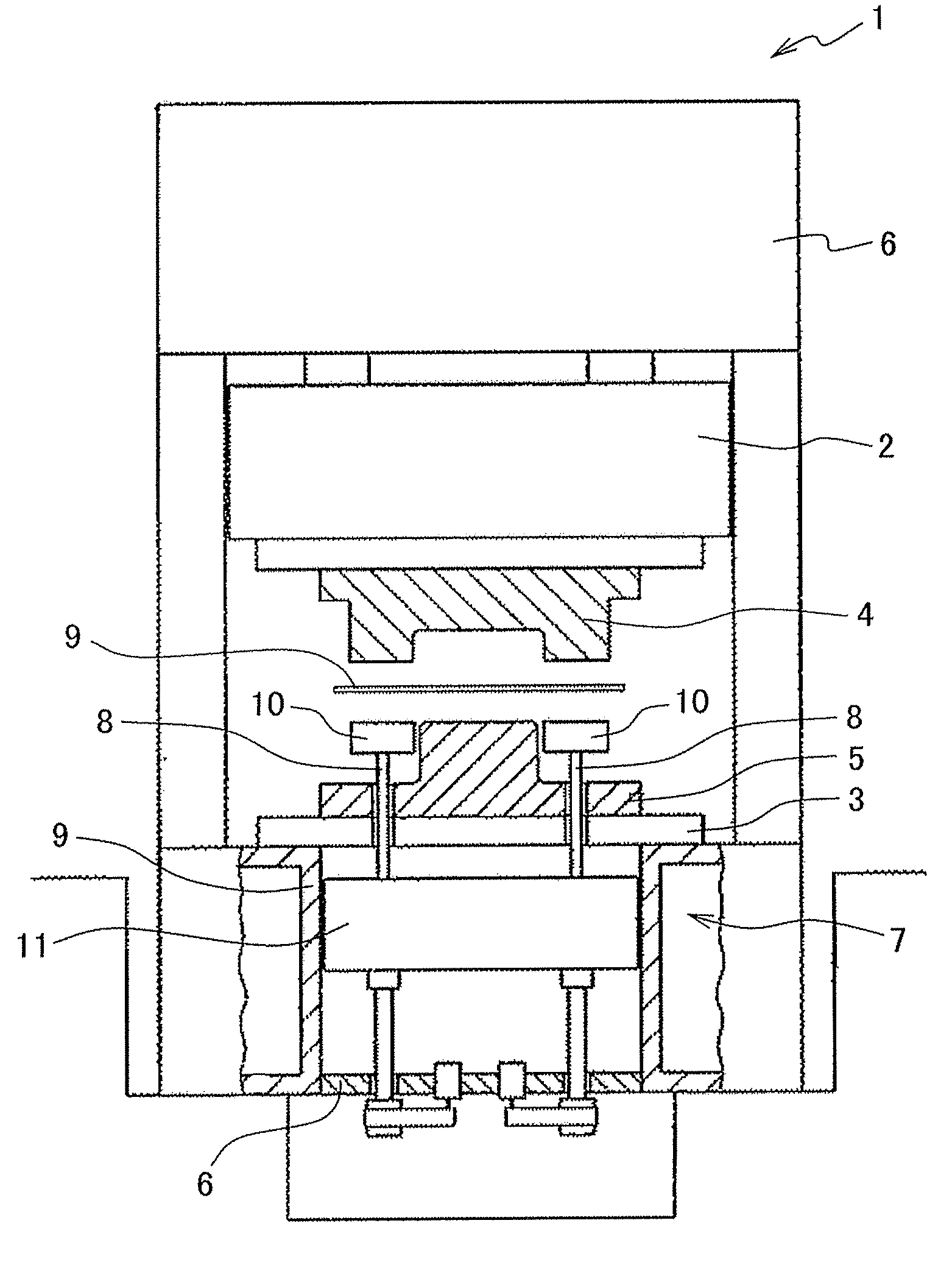
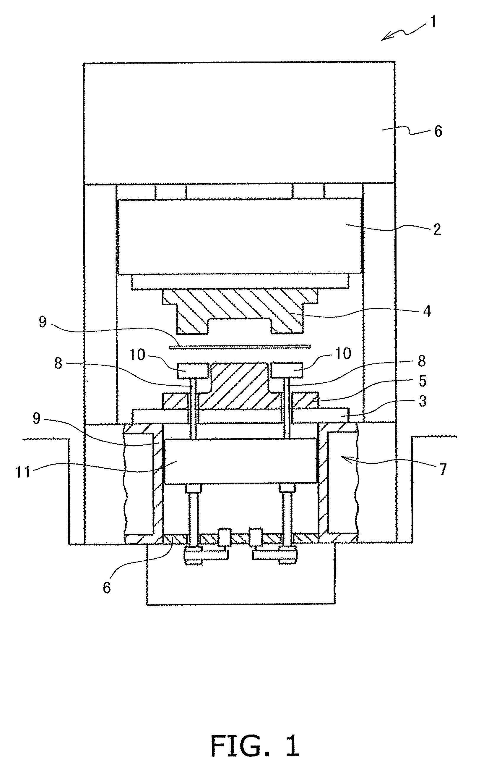
[0027]FIG. 1 is a schematic diagram illustrating the structure of a press machine 1. The press machine 1 includes a slide 2, a bolster 3, a pair of a top die 4 and a bottom die 5, a slide drive mechanism 6, and a die cushion device 7.

[0028]The slide 2 is disposed while being allowed to move in a vertical direction. The bolster 3 is disposed below and opposed to the slide 2. The slide drive mechanism 6 is disposed over the slide 2. The slide drive mechanism 6 is configured to raise and lower the slide 2. The top die 4 is attached to a bottom part of the slide 2. The bottom die 5 is attached to a top part of the bolster 3. Each of the bolster 3 and the bottom die 5 includes a plurality of through holes vertically penetrating therethrough. A plurality of cushion pins 8 described below are respectively inserted into the throu...


PUM

PropertyMeasurementUnit
speedaaaaaaaaaa
reaction forceaaaaaaaaaa
pressureaaaaaaaaaa

Abstract

A die cushion device includes a cushion pad, a support section, a servomotor, and a shock absorber device. The support section supports the cushion pad. The servomotor raises and lowers the support section for raising and lowering the cushion pad. The shock absorber device includes a damping section and relieves shock between the cushion pad and the support section. The damping section generates reaction force in accordance with the relative speed of the cushion pad with respect to the support section.

Description

CROSS-REFERENCE TO RELATED APPLICATIONS[0001]This national phase application claims priority to Japanese Patent Application No. 2008-134819 filed on May 22, 2008. The entire disclosure of Japanese Patent Application No. 2008-134819 is hereby incorporated herein by reference.TECHNICAL FIELD[0002]The present invention relates to a die cushion device.BACKGROUND ART[0003]The die cushion devices are installed in the press machines for applying press force to a slide. In the die cushion devices, a cushion pad receives force from the slide moving downwards. Further, the cushion pad is configured to be moved while applying press force to the slide.[0004]In the well-known die cushion devices, a servomotor is caused to drive the cushion pad for highly accurately controlling press force to be applied to the slide. Further, there has been produced a die cushion devices of a type configured to relieve shock in collision between the slide and the cushion pad (see Japan Laid-Open Patent Applicatio...

Claims


Application Information

Patent Timeline
Patent Type & Authority Applications(United States)
IPC IPC(8): B21D22/00
CPCB21D24/10B21D24/02
Inventor MIYASAKA, TAKUJISATO, HIROHIDEMORIMOTO, SHIGEOITO, HIROYUKIARIKABE, TAKEOWATANABE, SHYOJINAGASHIMA, SHIGENORI
Owner KOMATSU LTD
Why Eureka
Try Eureka