Hall effect thruster with cooling of the internal ceramic

a technology of internal ceramic and hall effect thruster, which is applied in the direction of accelerators, using plasma, electric discharge tubes, etc., can solve the problems of insufficient reduced overall performance and observed instability of hall effect thruster operation, etc., to achieve low or no instability, performance that is not decreased, and lifetime that is not decreased

Active Publication Date: 2011-03-17
SN DETUDE & DE CONSTR DE MOTEURS DAVIATION S N E C M A
View PDF7 Cites 17 Cited by
  • Summary
  • Abstract
  • Description
  • Claims
  • Application Information

AI Technical Summary

Benefits of technology

[0015]The invention proposes a Hall effect thruster that presents little or no instability while starting, performance that is not decreased, even over the long term, and a lifetime that is not decreased.
[0016]This object is achieved by the fact that the Hall effect thruster includes a heat sink device comprising a heat sink in contact with the inner wall and of thermal conductivity that is greater than the thermal conductivity of the inner wall, the heat sink being a sleeve and the heat sink device being suitable for discharging heat from the inner wall to the outside of the thruster so as to reduce the temperature difference between the inner wall and the outer wall.
[0017]By means of these dispositions, the temperature difference between the inner wall and the outer wall is reduced. Simulations undertaken by the inventors have shown that this reduction contributes to stabilizing the ejection of ions from the discharge channel. This phenomenon is due to the fact that the energy dispersion of the population of electrons that ionize the gas atoms is then reduced, and also to the fact that the atoms of non-ionized gas that strike the cooler, inner wall present energy that is less dispersed.

Problems solved by technology

When starting the Hall effect thruster, and after a repeated number of such starts, the operation of the Hall effect thruster is observed to become unstable, i.e. ions are ejected from the discharge channel in a manner that is not stable over time.
This instability generates magnetic emissions that lead to insufficient performance from the Hall effect thruster.
However that solution reduces the overall performance of the Hall effect thruster.
It is also possible to correct the instability by modifying the magnetic field B. However that correction requires an additional electronic device to be installed and used, thus necessarily consuming energy and thus making the Hall effect thruster more expensive to fabricate and presenting a lifetime that is shorter.

Method used


Image

  • Hall effect thruster with cooling of the internal ceramic
  • Hall effect thruster with cooling of the internal ceramic

Examples


Embodiment Construction

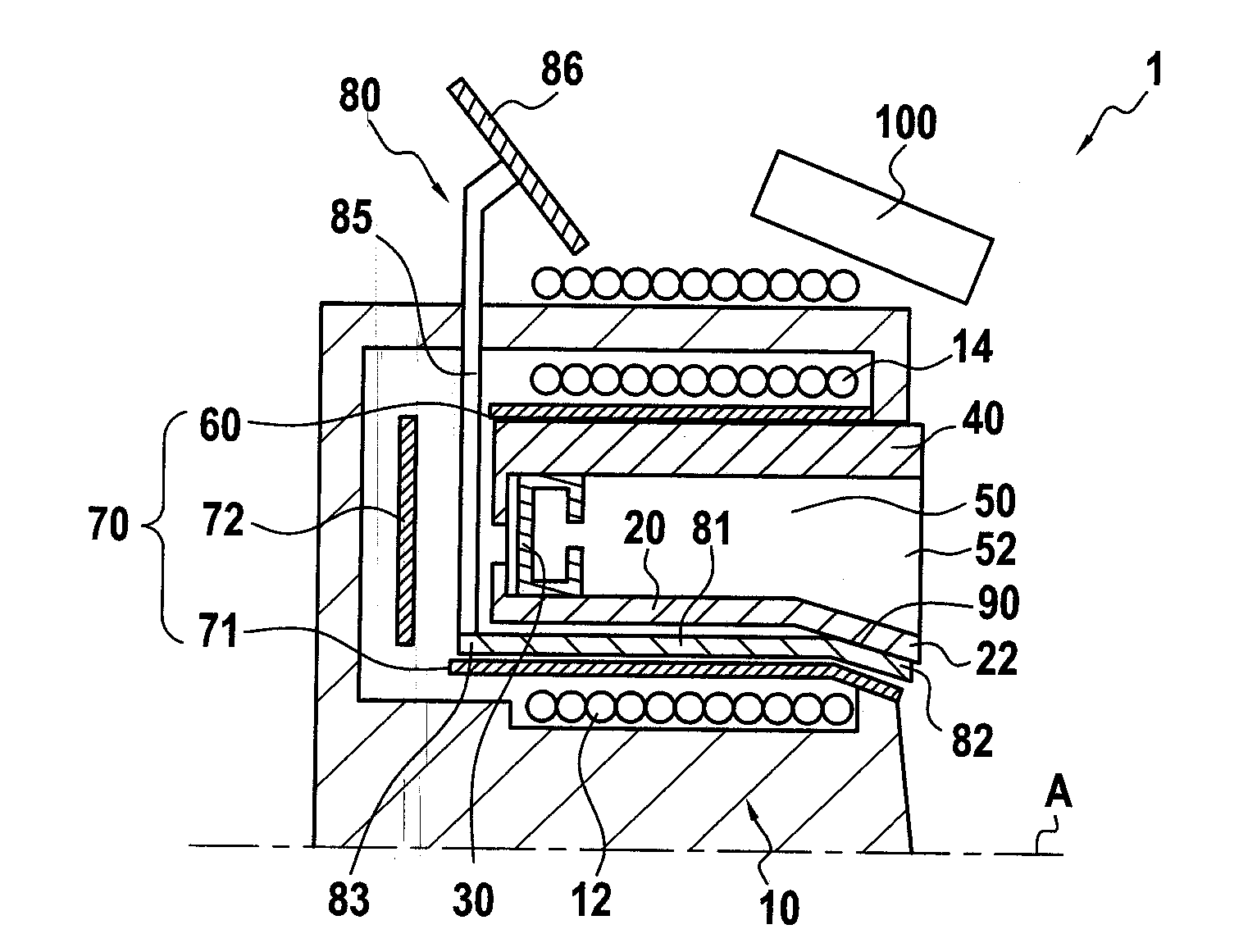
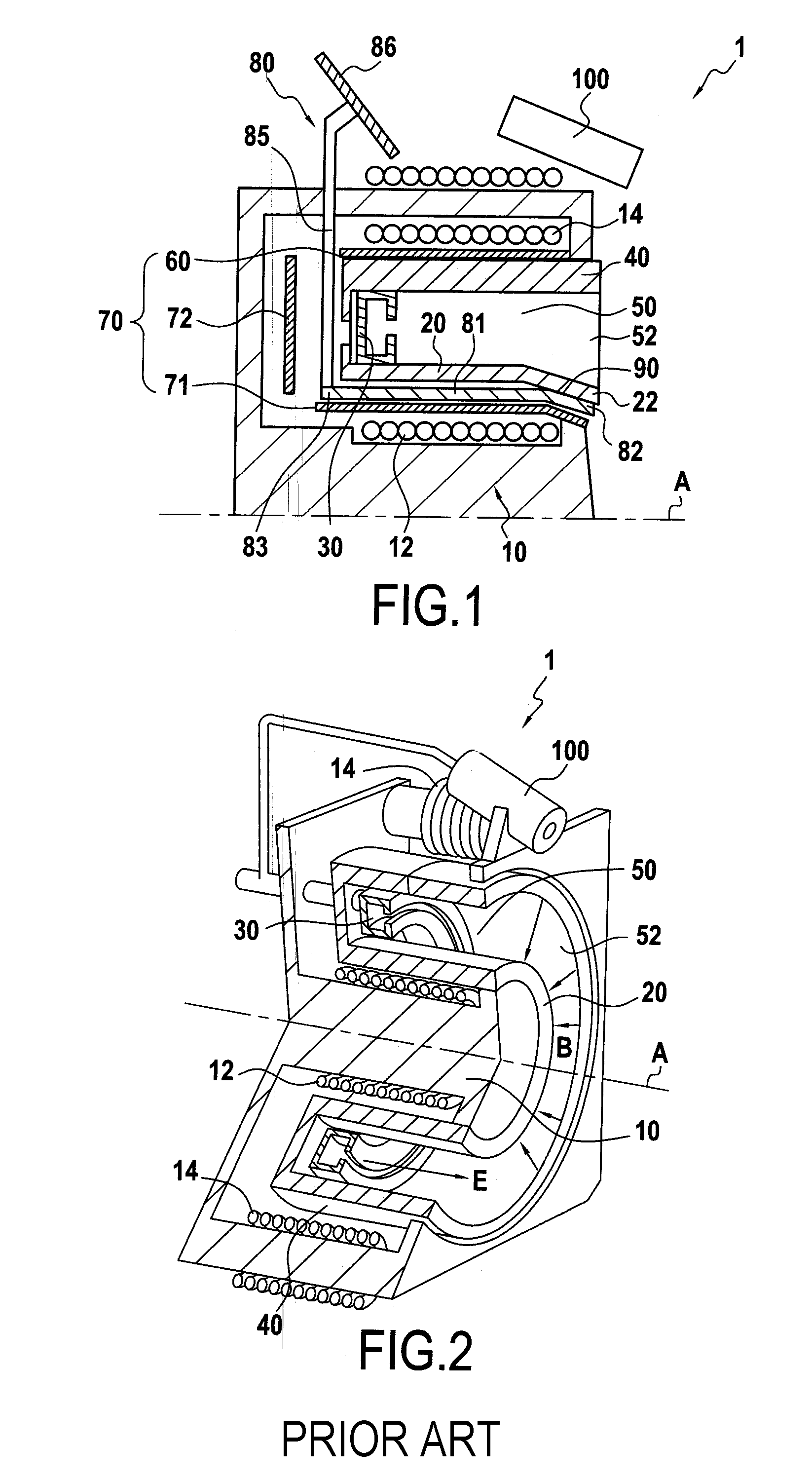
[0021]FIG. 1 shows a Hall effect thruster of the invention in longitudinal section. For reasons of symmetry, only half of the thruster on one side of the longitudinal axis A is shown, the cathode 100 also being shown. Parts that are common with the prior art Hall effect thruster shown in FIG. 2 are given identical references and are therefore not described again.

[0022]During operation of the Hall effect thruster 1, electrons penetrate into the discharge channel 50 from its downstream end 52 and are forced by the radial magnetic field B to follow substantially circumferential trajectories in the vicinity of said downstream end 52. Some of these electrons strike the inner wall 20 and the outer wall 40 of the discharge channel 50. In addition, some of the ions which are accelerated from upstream towards the downstream end 52 of the discharge channel and some of the non-ionized atoms strike these walls (these ions come from ionization of atoms injected by the injector system 30 into the...


PUM


Abstract

The invention relates to the field of Hall effect thrusters. The invention provides a Hall effect thruster having a discharge channel of annular shape extending along an axis, the discharge channel being defined by an outer wall of annular shape and an inner wall of annular shape situated inside the space defined by the outer wall, a cathode situated outside the discharge channel, and an injector system situated at the upstream end of the discharge channel and also forming an anode, the downstream end of the discharge channel being open, wherein the thruster includes a heat sink device comprising a heat sink in contact with the inner wall and of thermal conductivity that is greater than the thermal conductivity of the inner wall, the heat sink being a sleeve and the heat sink device being suitable for discharging heat from the inner wall to the outside of the thruster so as to reduce the temperature difference between the inner wall and the outer wall.

Description

FIELD OF THE INVENTION[0001]The present invention relates to a Hall effect thruster having a discharge channel of annular shape extending along an axis, the discharge channel being defined by an outer wall of annular shape and an inner wall of annular shape situated inside the space defined by the outer wall, a cathode situated outside the discharge channel, and an injector system situated at the upstream end of the discharge channel and also forming an anode, the downstream end of the discharge channel being open.[0002]A Hall effect thruster is a thruster used in the field of space propulsion, for example, since it enables spacecraft to be propelled in the vacuum of space while using a mass of fuel that is less than would be necessary for a chemically-fueled thruster, and it presents a lifetime that is long: several thousands of hours.BACKGROUND OF THE INVENTION[0003]Since the Hall effect thruster is known, its structure and its operating principle are briefly summarized below.[000...

Claims


Application Information

Patent Timeline
Patent Type & Authority Applications(United States)
IPC IPC(8): H05H7/00
CPCF03H1/0031F03H1/0075
Inventor MARCHANDISE, FREDERICLEROI, VAITUAZURBACH, STEPHANINDERSIE, DOMINIQUE
Owner SN DETUDE & DE CONSTR DE MOTEURS DAVIATION S N E C M A
Why Eureka
Try Eureka