Offset amount calibrating method and surface texture measuring machine

Active Publication Date: 2011-04-14
MITUTOYO CORP
View PDF3 Cites 9 Cited by
  • Summary
  • Abstract
  • Description
  • Claims
  • Application Information

AI Technical Summary

Benefits of technology

[0014]An object of the present invention is to provide an offset amount calibrating method for a surface texture measuring machine equipped with a contact-type detector and an image probe, being capable of accurately and efficiently obtaining the offset amount between the contact-type detector and the image probe, and a surface texture measuring machine using the same.
[0017]As described above, the offset amount is obtained from the difference between the reference position of the calibration chart obtained based on the image captured by the image probe and the reference position of the calibration chart obtained based on the measurement by the contact-type detector. Thus, the offset amount between the contact-type detector and the image probe can be accurately and efficiently obtained.
[0019]With the above arrangement, even when the calibration chart is not accurately oriented at the time of setting the calibration chart on the stage, the calibration chart can be set in an orientation allowing the contact-type detector to measure at least two of the linewidth patterns of the calibration chart in the second calibration measuring step. Thus, the calibration can be efficiently performed.
[0025]In this manner, the stylus of the contact-type can be automatically set at the measurement starting position on the object. In other words, an operator does not have to set the tip end of the stylus at the measurement starting position on the object while visibly checking and adjusting the position of the tip end of the stylus relative to the measurement starting position on the object as in a typical apparatus. Therefore, the stylus can be prevented from interfering with the object while the burden on the operator can be reduced.

Problems solved by technology

Accordingly, the above setting operation of a stylus, which is quite complicated and requires a long time, places a large burden on an operator.
In addition, some types of objects may interfere with (collide with) a stylus to damage the stylus or the objects.

Method used


Image

  • Offset amount calibrating method and surface texture measuring machine
  • Offset amount calibrating method and surface texture measuring machine
  • Offset amount calibrating method and surface texture measuring machine

Examples


Embodiment Construction

Description of Surface Texture Measuring Machine (Reference to FIGS. 1 to 5)

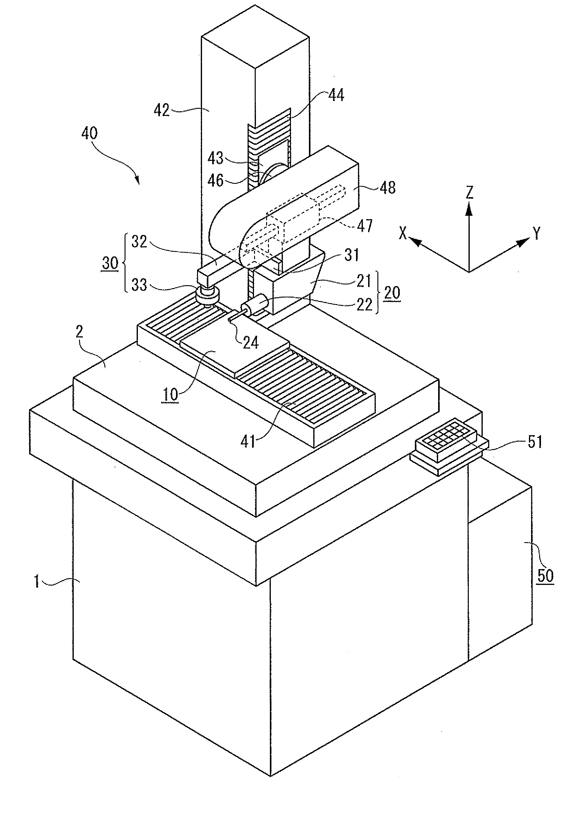
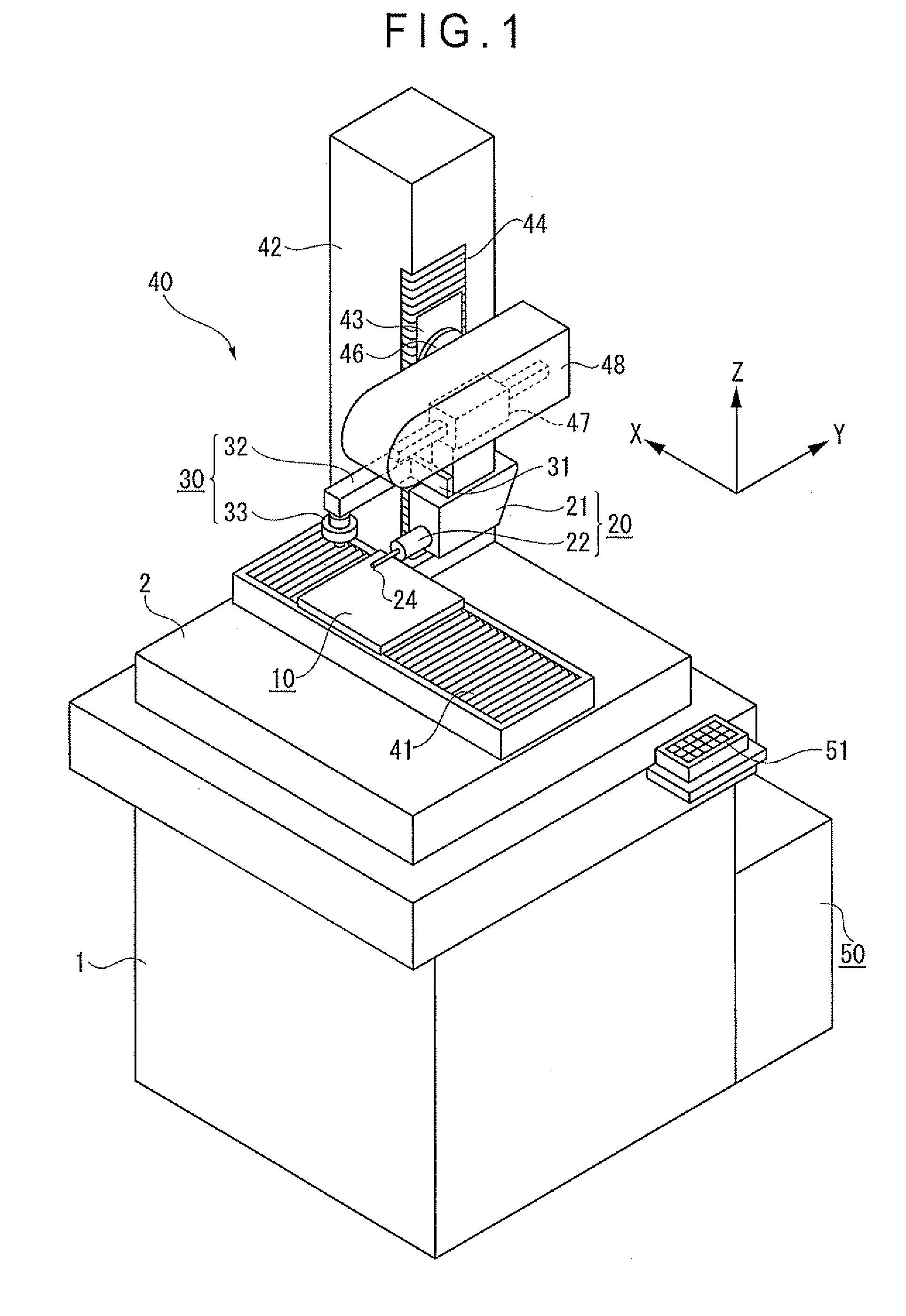
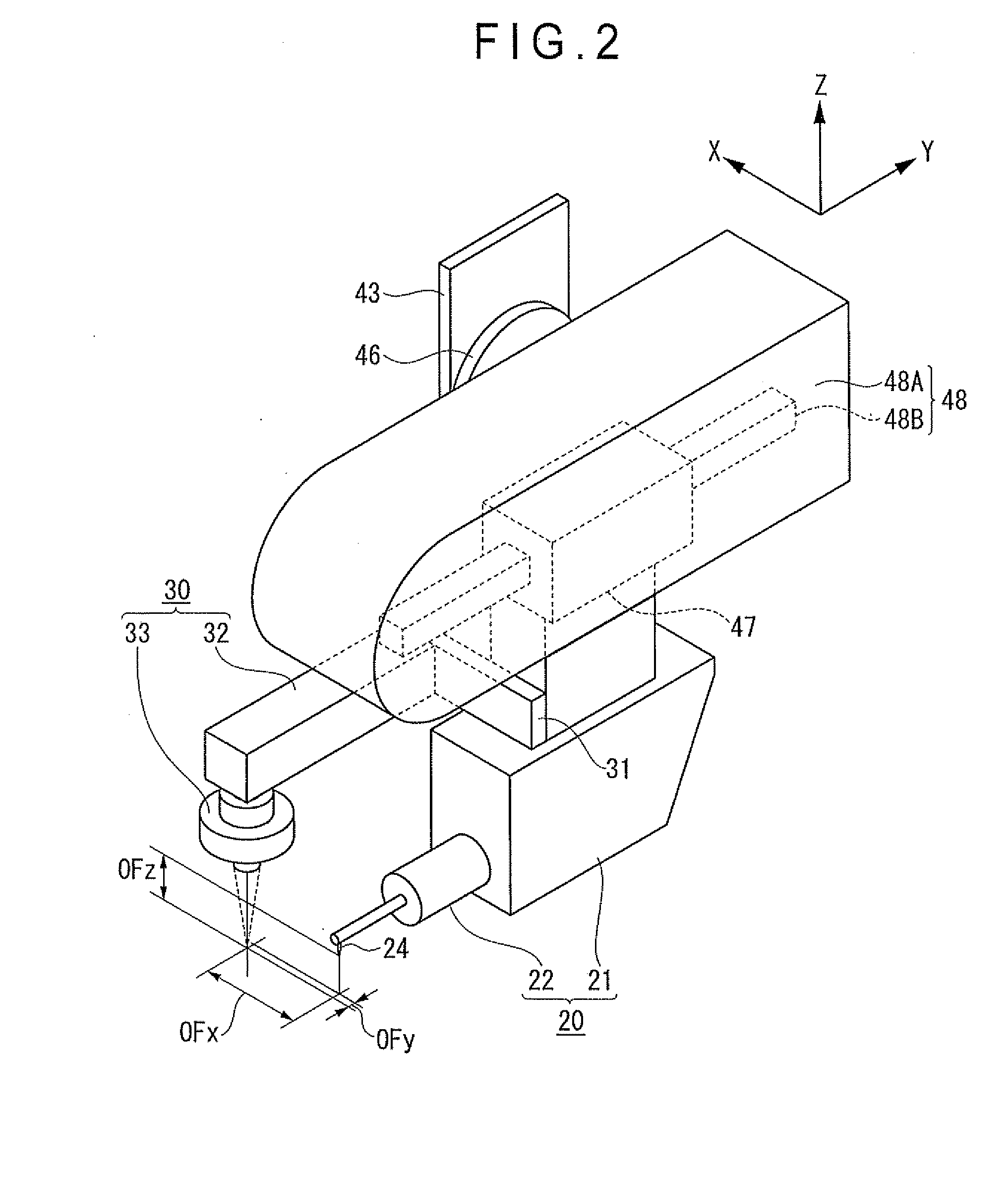
[0036]As shown in FIGS. 1 and 2, a surface texture measuring machine according to an exemplary embodiment of the present invention includes: a mount stand 1; a base 2 being fixed on the upper surface of the mount stand 1; a stage 10 being mounted on the base 2, the stage 10 having an upper surface on which an object is mounted; a contact-type detector 20 being provided with a stylus 24 that is brought into contact with a surface of the object; an image probe 30 that captures the image of the surface of the object; a relative movement mechanism 40 that relatively moves the contact-type detector 20 and the image probe 30 against the stage 10 and moves the stage 10 against the contact-type detector 20 and the image probe 30; and a controller 50.

[0037]The relative movement mechanism 40 includes: an X-axis driving mechanism 41 as a first movement mechanism being located between the base 2 and the stage 10 to move...


PUM


Abstract

An offset amount calibrating method that obtains the offset amount between a contact-type detector and an image probe is provided. The method includes: setting on a stage a calibration chart that includes not less than two non-parallel linewidth patterns being disposed relative to a reference position of the calibration chart and each having a known width and a level difference; capturing an image of the linewidth patterns of the calibration chart by an image probe to obtain the reference position of the calibration chart; measuring at least two of the linewidth patterns of the calibration chart by a contact-type detector to obtain the reference position of the calibration chart; and calculating a difference between the reference position obtained by using the image probe and the reference position obtained by using the contact-type detector to obtain the offset amount.

Description

[0001]The entire disclosure of Japanese Patent Application No. 2009-236126 filed Oct. 13 2009 is expressly incorporated by reference herein.BACKGROUND OF THE INVENTION[0002]1. Field of the Invention[0003]The present invention relates to a surface texture measuring machine equipped with a contact-type detector with a stylus and an image probe and to an offset amount calibrating method for obtaining the offset amount between the contact-type detector and the image probe.[0004]2. Description of Related Art[0005]There has been known a surface texture measuring machine in which a stylus is moved along a surface of an object while being in contact with the surface of the object. The displacement of the stylus due to the surface profile or surface roughness of the object is detected, thereby measuring the surface texture such as the surface profile, surface roughness or the like of the object based on the displacement of the stylus (see, for instance, Patent Literature: JP-A-05-087562).[00...

Claims


Application Information

Patent Timeline
IPC IPC(8): G01B11/24
CPCG01B5/008G01B21/042G01B11/005
Inventor TAKAHASHI, TOMOTAKA
Owner MITUTOYO CORP
Why Eureka
Try Eureka