
Navigation device for joint replacement and surgical support device

Active Publication Date: 2015-06-11
ARTHRO DESIGN +2
View PDF3 Cites 21 Cited by
  • Summary
  • Abstract
  • Description
  • Claims
  • Application Information

AI Technical Summary

Benefits of technology

This patent aims to reduce the burden on patients and operators and create a better experience for artificial joint replacement. This is achieved by using a guide instrument that is installed during preoperative planning. This results in a more efficient and effective joint replacement process.

Problems solved by technology

Of these, the method (1) does not require a processing for preoperative image acquisition, but cannot be said to be satisfactory in accuracy of the navigation.

Method used


Image

  • Navigation device for joint replacement and surgical support device
  • Navigation device for joint replacement and surgical support device
  • Navigation device for joint replacement and surgical support device

Examples


embodiment 1

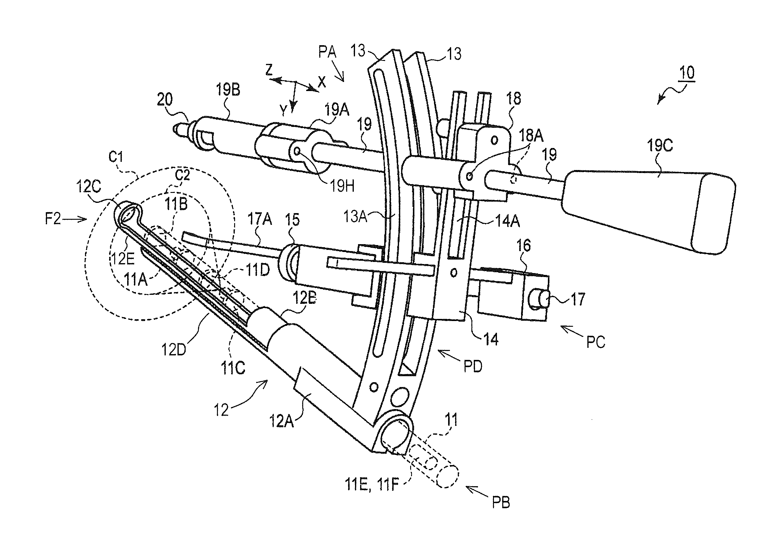
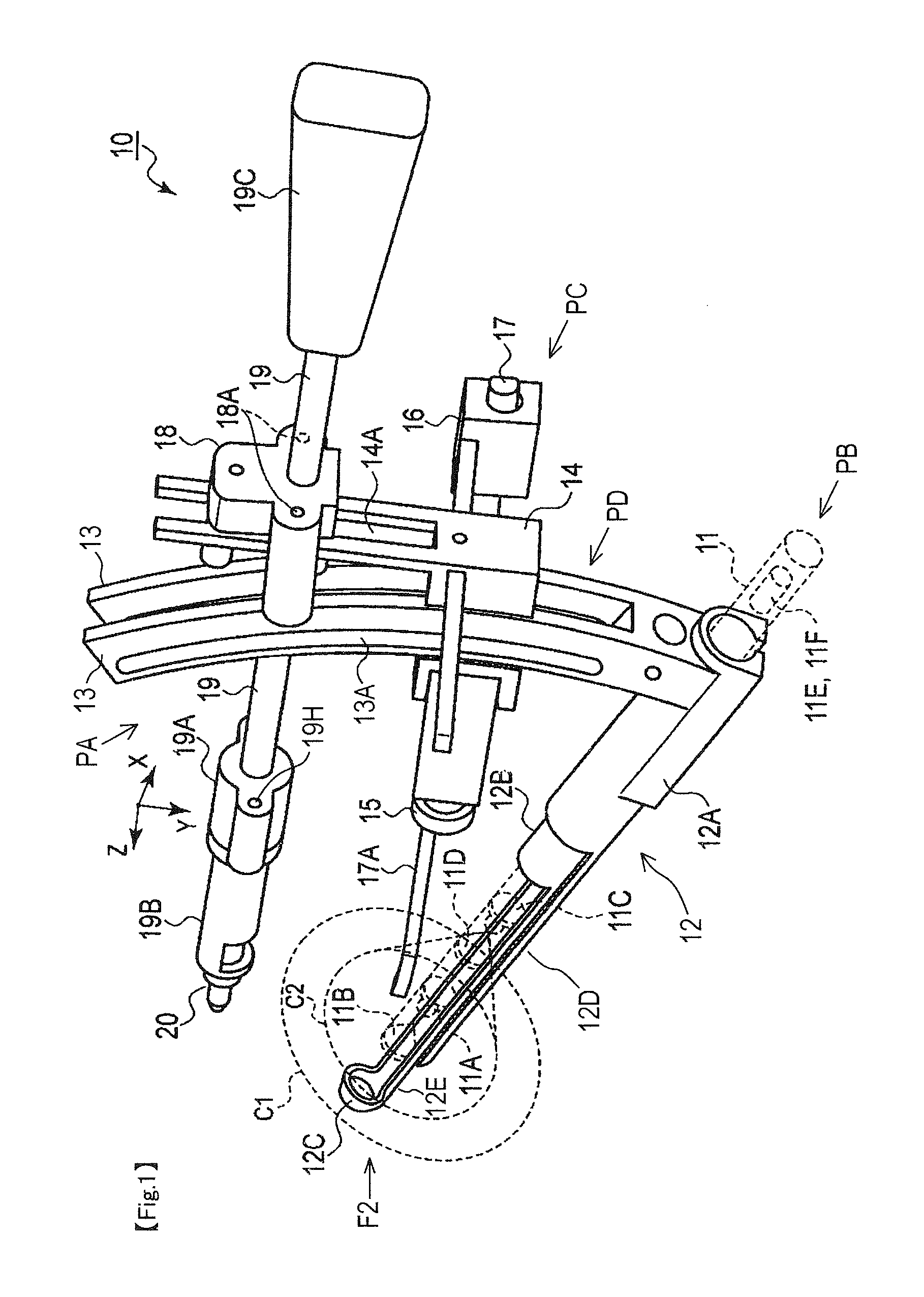
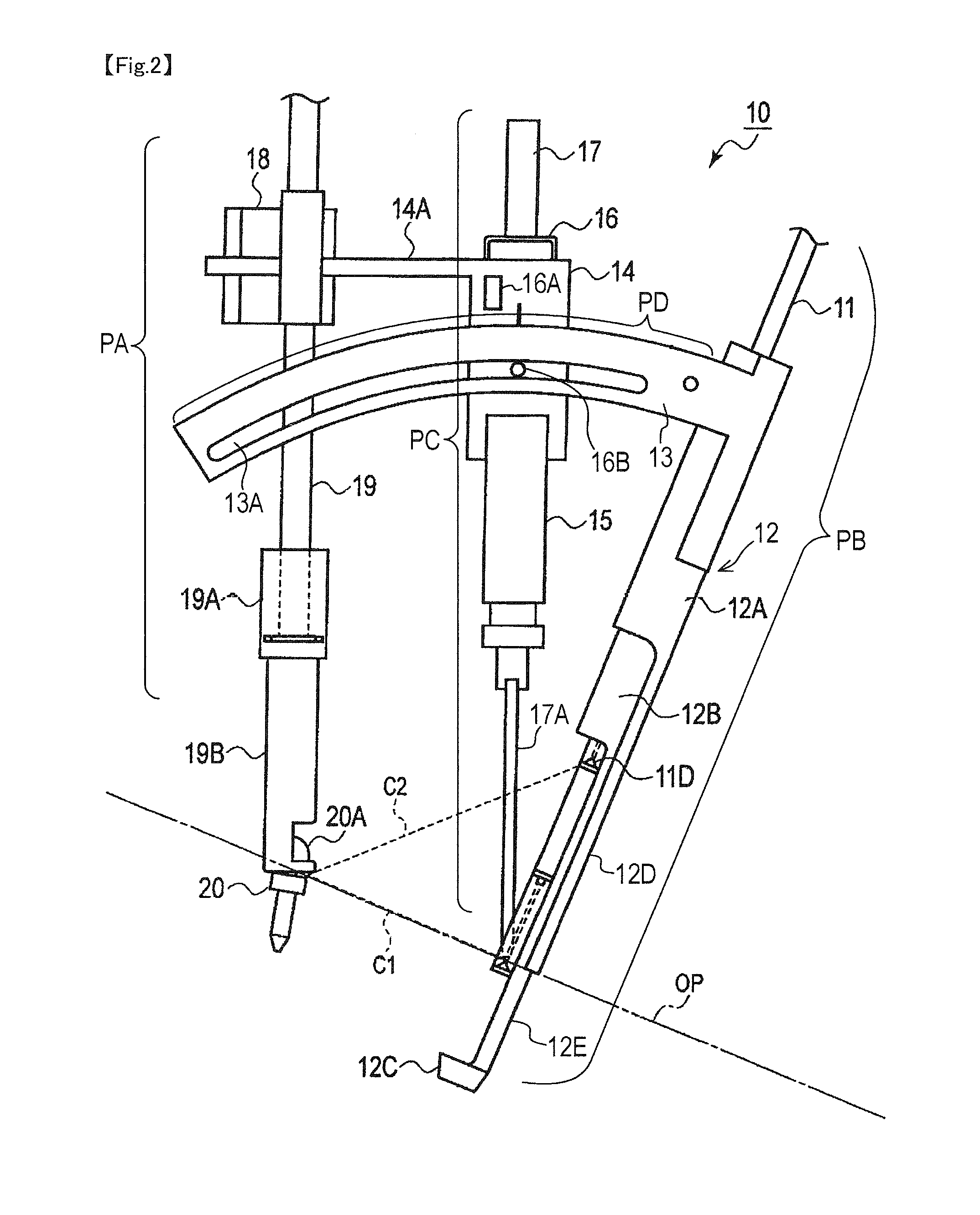
[0023]Next, an embodiment 1 of the present invention will be described. First, a guide instrument for artificial joint replacement (hereinafter, simply referred to as a “guide instrument”) used in this embodiment will be described with reference to FIGS. 1 to 4. FIGS. 1 to 4 are those filed in Japanese Patent Application No. 2012-36256. A perspective view of a guide instrument 10 is shown in FIG. 1, and a side thereof as viewed from a direction of an arrow F2 is shown in FIG. 2. In these drawings, the guide instrument 10 is broadly constituted of

a. a fixing support unit PA fixing and supporting the instrument itself to the pelvis;

b. an operating unit PB to which a shape measuring instrument or a drill is attached;

c. an imaging unit PC detecting a signal from the shape measuring instrument; and

d. a positioning arm unit PD for adjusting the positions of the operating unit PB and imaging unit PC with respect to the fixing support unit PA.

[0024]

[0025]Of these, the fixing support unit PA...


PUM


Abstract

CT images near the pelvis are obtained before surgery, and a three-dimensional model of a pelvis part is created on a computer. The virtual three-dimensional bone model is used to plan an installation position of a guide instrument etc., and a virtual three-dimensional surgical site model including the guide instrument is constructed. Subsequently, during surgery, the guide instrument is installed, and three-dimensional images of a surgical site are obtained, and a measured three-dimensional surgical site model including the guide instrument is obtained. The virtual three-dimensional surgical site model and the measured three-dimensional surgical site model are compared, and an error between an ideal installation position of the guide instrument and an actual installation position of the guide instrument is detected to guide the operator to reduce the error.

Description

TECHNICAL FIELD[0001]The present invention relates to a navigation device for joint replacement and a surgical support device which provide support or navigation by computer in implanting an artificial hip joint component, for example.BACKGROUND ART[0002]In performing an artificial joint replacement such as a knee or hip, support or navigation by computer is used to accurately implant an artificial joint component (part). Broadly speaking, there is the following technique (see Non-Patent Literature 1):(1) A method of providing navigation by using motion information, etc., obtained by moving a joint, without using image information of a joint part by CT (Computed Tomography); and(2) A method of providing navigation by using image information by CT to prepare a three-dimensional (3D) bone shape model, and registering it to an intraoperative bone shape.[0003]Of these, the method (1) does not require a processing for preoperative image acquisition, but cannot be said to be satisfactory ...

Claims


Application Information

Patent Timeline
IPC IPC(8): A61F2/46
CPCA61F2/4609A61F2002/4663A61F2002/4632A61F2/4657A61B5/055A61B2034/102A61B2034/2048A61B90/30A61B90/11A61B2034/105A61B90/35
Inventor WAKAYAMA, TOSHITAKAKITO, YUKARISEITOKU, NORIOHANDA, TAKASHIYOSHIZAWA, TORU
Owner ARTHRO DESIGN
Learn More