Television receiver and method for driving television receiver

a technology for television receivers and receivers, applied in the field of television receivers, can solve the problems of interior spoilage even more, and the effort can only achieve so much in improving the interior usability of television receivers, and achieve the effect of higher surface luminance and higher surface luminan

Inactive Publication Date: 2011-06-09
SHARP KK
View PDF16 Cites 3 Cited by
  • Summary
  • Abstract
  • Description
  • Claims
  • Application Information

AI Technical Summary

Benefits of technology

[0087]As described above, the television receiver of the present invention, while the display region displays a decorative image, displays a decorative frame in a peripheral section of the decorative image, and in the display region, a part of the display region in which the decorative frame is displayed has a higher surface luminance as compared to a surface luminance in a part of the display region in which the decorative image is displayed.
[0088]Moreover, as described above, a method of the present invention for driving a television receiver is a method in which, while the display region displays the decorative image, the display region is caused to display a decorative frame in a peripheral section of the decorative image, and in the display region, a part in the display region in which the decorative frame is displayed has a higher surface luminance as compared to a surface luminance in a part of the display region in which the decorative image is displayed.
[0089]This attains an effect of providing a television receiver and a method for driving the television receiver, which television receiver, in a case where a decorative image such as a painting or photograph is displayed in a display region of the television receiver, displays the decorative image as though the decorative image had a real frame, so that the television receiver can be utilized as a part of the interior.

Problems solved by technology

However, this attempt can only achieve so much in improving the interior usability of the television receiver; it is the display region that occupies most part of the appearance of the television receiver, which display region gives the strongest impression.
Due to the enlargement of recent television receivers, the interior is spoiled even more than before.

Method used


Image

  • Television receiver and method for driving television receiver
  • Television receiver and method for driving television receiver
  • Television receiver and method for driving television receiver

Examples


embodiment 1

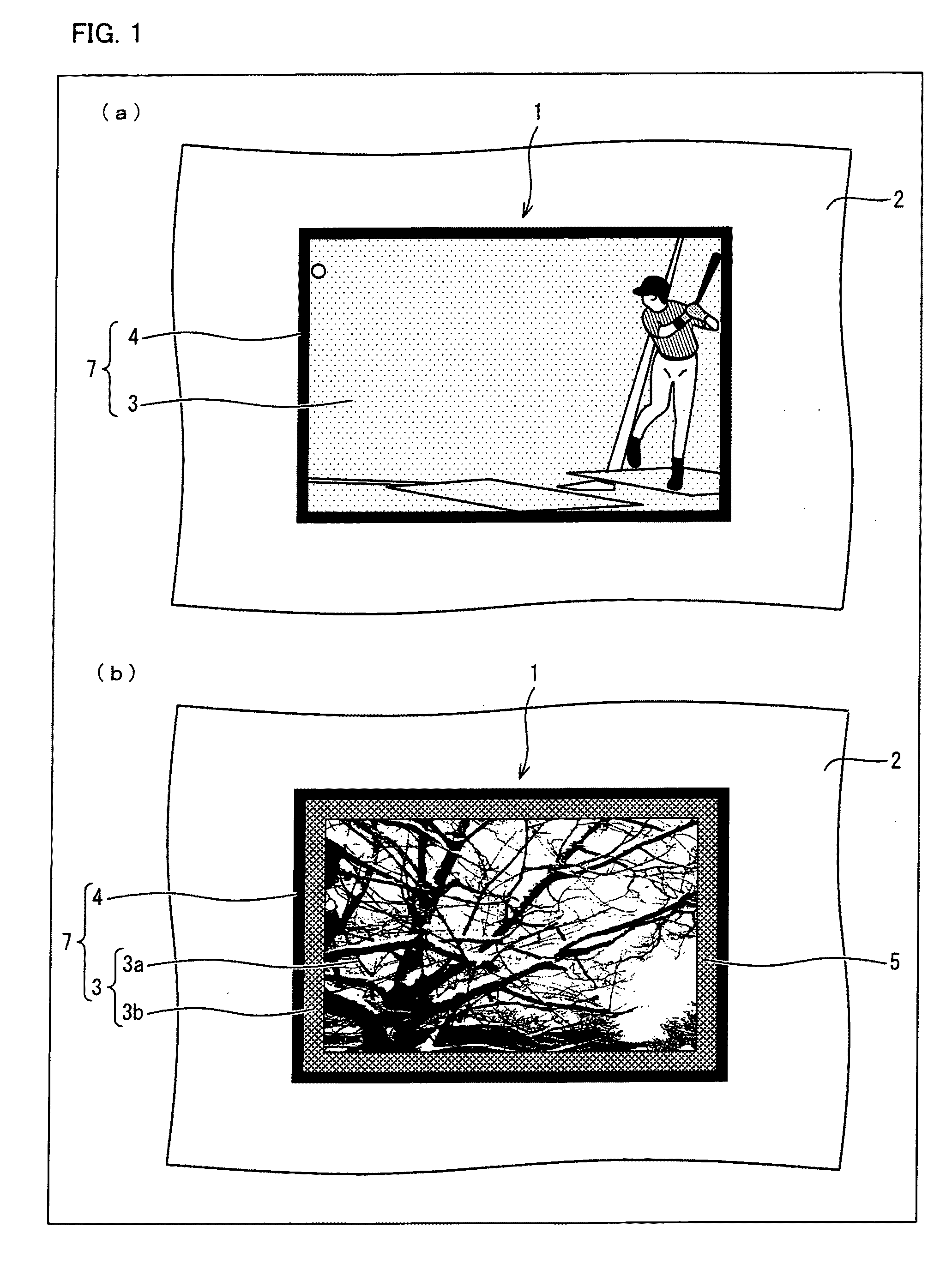
[0101]The following description specifically explains one embodiment of the present invention by use of a liquid crystal television receiver as an example, in which a display region of the television receiver is made of a screen of a liquid crystal display device.

[0102]A liquid crystal television receiver in which this liquid crystal display device is used can be provided on the wall due to its light weight and its thin thickness.

[0103]However, the liquid crystal display device has an entirely black display surface while its display is turned off. Consequently, while the television receiver disposed on the wall is turned off, the wall will have a black object thereon.

[0104]This black object spoils the interior. Due to the enlargement of recent television receivers, the interior is spoiled even more than before.

[0105]On this account, the liquid crystal television receiver of the present embodiment has, other than the original function for displaying image data such as broadcasting an...

embodiment 2

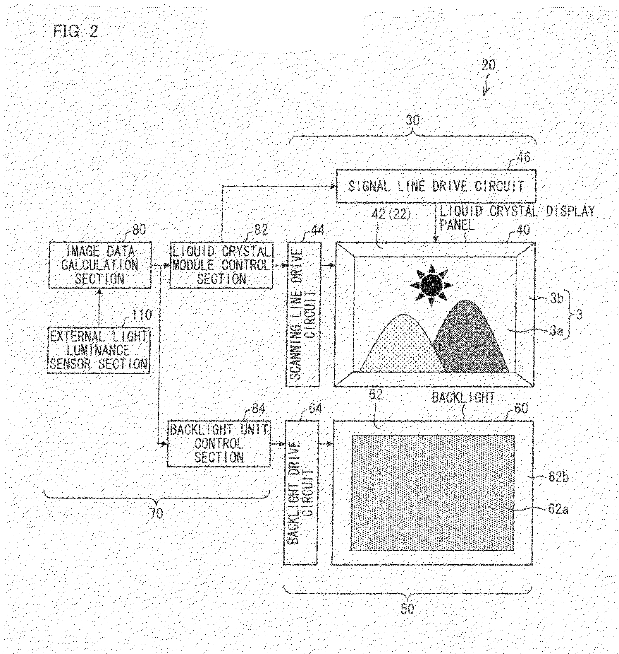
[0251]The following description explains the liquid crystal display device 20 according to the present invention, and further other features of the liquid crystal television receiver 1 that employs the liquid crystal display device 20. The descriptions will be given one by one.

[0252]Configurations other than what is particularly described in the following descriptions are the same as Embodiment 1. Moreover, for easy description, members that have identical functions as the members illustrated in the drawings of Embodiment 1 are provided with identical reference signs, and their descriptions are omitted.

[0253]

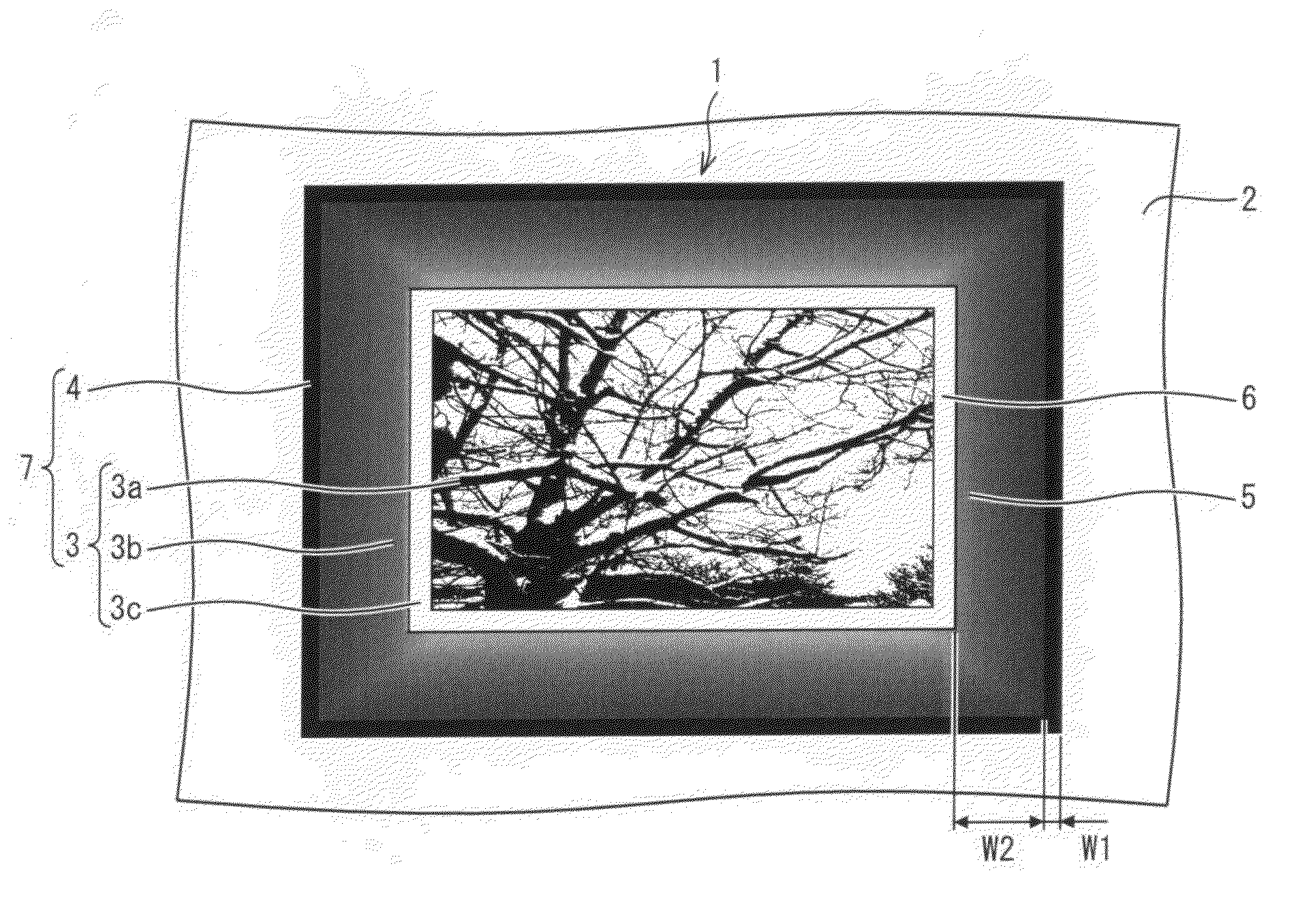
[0254]FIGS. 5 to 9 are views each illustrating a liquid crystal television receiver 1 of an embodiment of the present invention in the picture mode, which each liquid crystal television receiver is hung on the wall 2.

[0255]FIG. 10 is a view illustrating a Munsell hue circle having 20 hues.

[0256]In order to further improve the interior usability, the liquid crystal television rec...


PUM


Abstract

A decorative image is displayed in a decorative image display region; in the decorative image, a decorative frame is displayed in a peripheral section of a decorative frame display region, and the decorative frame display region has a surface luminance higher than that of the decorative image display region.

Description

TECHNICAL FIELD[0001]The present invention relates to a television receiver employing a display mode that makes a frame structure that is an actual part of the television receiver less conspicuous, while displaying a decorative image such as a painting or photograph on a display region of the television receiver, and relates to a method for driving such a television receiver.BACKGROUND ART[0002]In recent years, development of electronic apparatuses and like apparatuses for home use which can be utilized as a part of an interior of the home have been increasing in demand; such apparatuses serve as interior by making good use of their design while the apparatuses are not being used.[0003]Among such apparatuses, television receivers have increased in their presence due to the recent development in size, and hence the foregoing demand of developing the apparatuses utilizable as a part of the interior is increasing even more.[0004]On this account, attempts have been made with the televis...

Claims


Application Information

Patent Timeline
Patent Type & Authority Applications(United States)
IPC IPC(8): H04N5/445
CPCH04N5/445H04N21/44008H04N21/431H04N21/42202
Inventor ICHIOKA, HIDEKIKUSUMOTO, TOSHIHARUNISHIDA, KENJIUEKANE, KENTARO
Owner SHARP KK
Why Eureka
Try Eureka