Hole Cutter with Axially-Elongated Aperture Defining Multiple Fulcrums

a technology of axial extension and aperture, which is applied in the field of hole cutters, can solve the problems of time-consuming and laborious manual slug removal tasks, and difficulty in extracting slugs from within, and achieve the effect of convenient alignment of fulcrums

Active Publication Date: 2011-07-14
BLACK & DECKER INC
View PDF34 Cites 49 Cited by
  • Summary
  • Abstract
  • Description
  • Claims
  • Application Information

AI Technical Summary

Benefits of technology

[0016]One advantage of the hole cutters of the present invention is that they can provide a relatively quick, easy, and effective means to extract slugs from inside the hole cutters. Another advantage of the hole cutters of the present invention is that they provide multiple fulcrums at different axial locations, and in some embodiments, angular locations, to facilitate aligni

Problems solved by technology

This manual slug removal task can be time-consuming and take substantial effort on the part of the user.
A slug may be difficult to extract from within the body of a cutter, even with a hole cutter that includes slug removal apertures or slots, because the slug can become tightly wedged in the cutter or because the slug removal apertures or slots are not align

Method used


Image

  • Hole Cutter with Axially-Elongated Aperture Defining Multiple Fulcrums
  • Hole Cutter with Axially-Elongated Aperture Defining Multiple Fulcrums
  • Hole Cutter with Axially-Elongated Aperture Defining Multiple Fulcrums

Examples


Embodiment Construction

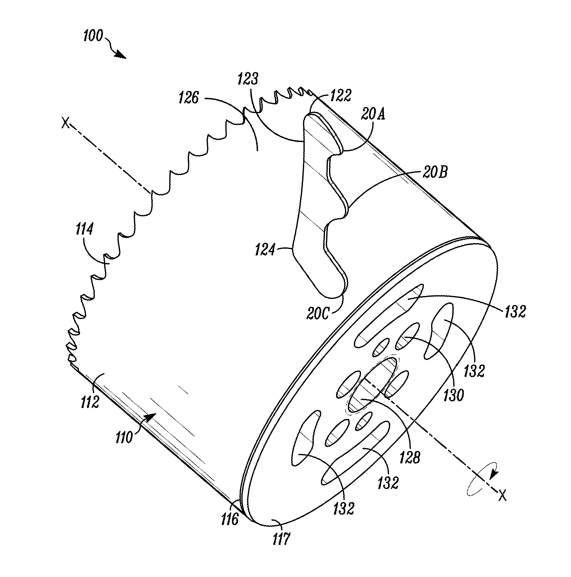
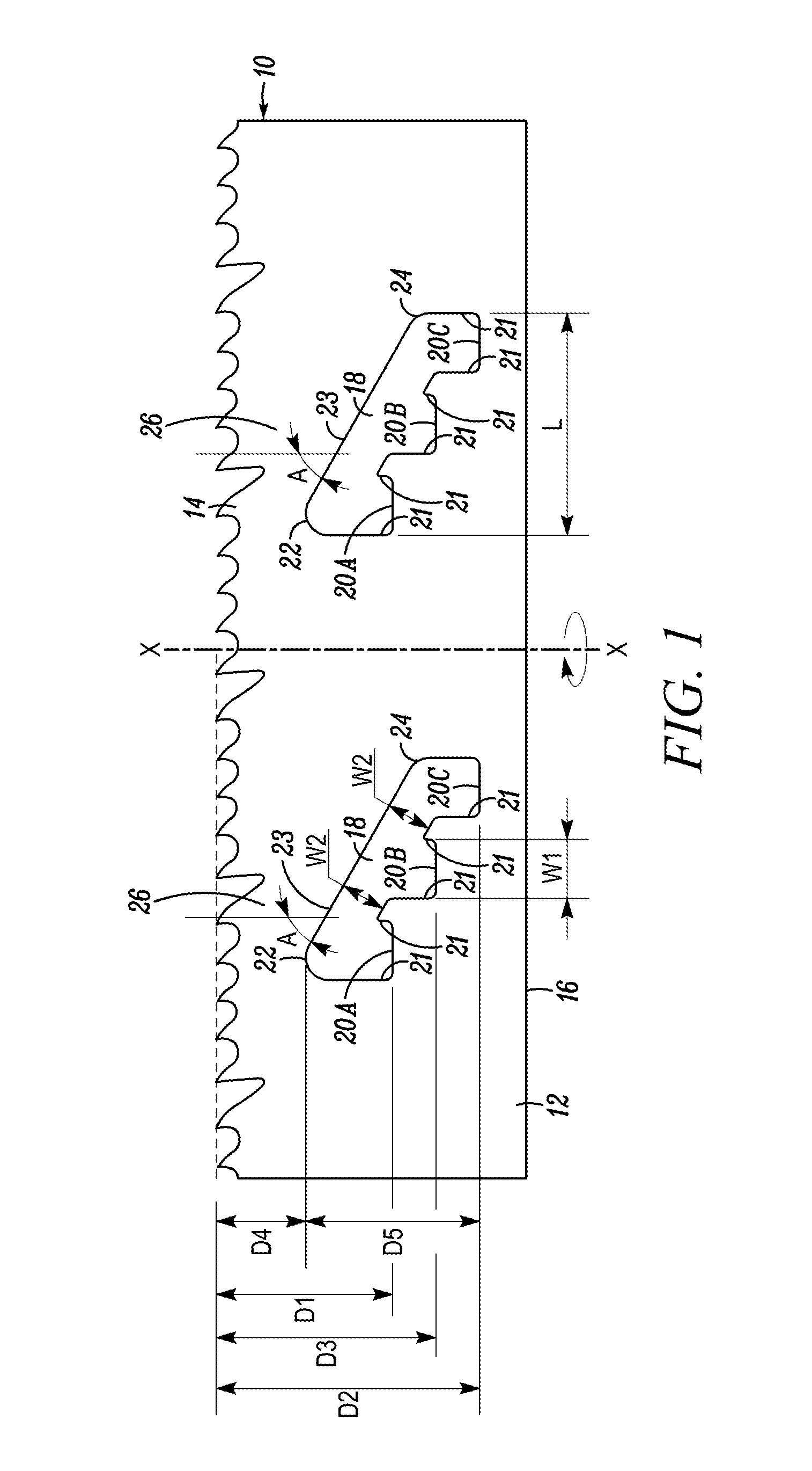
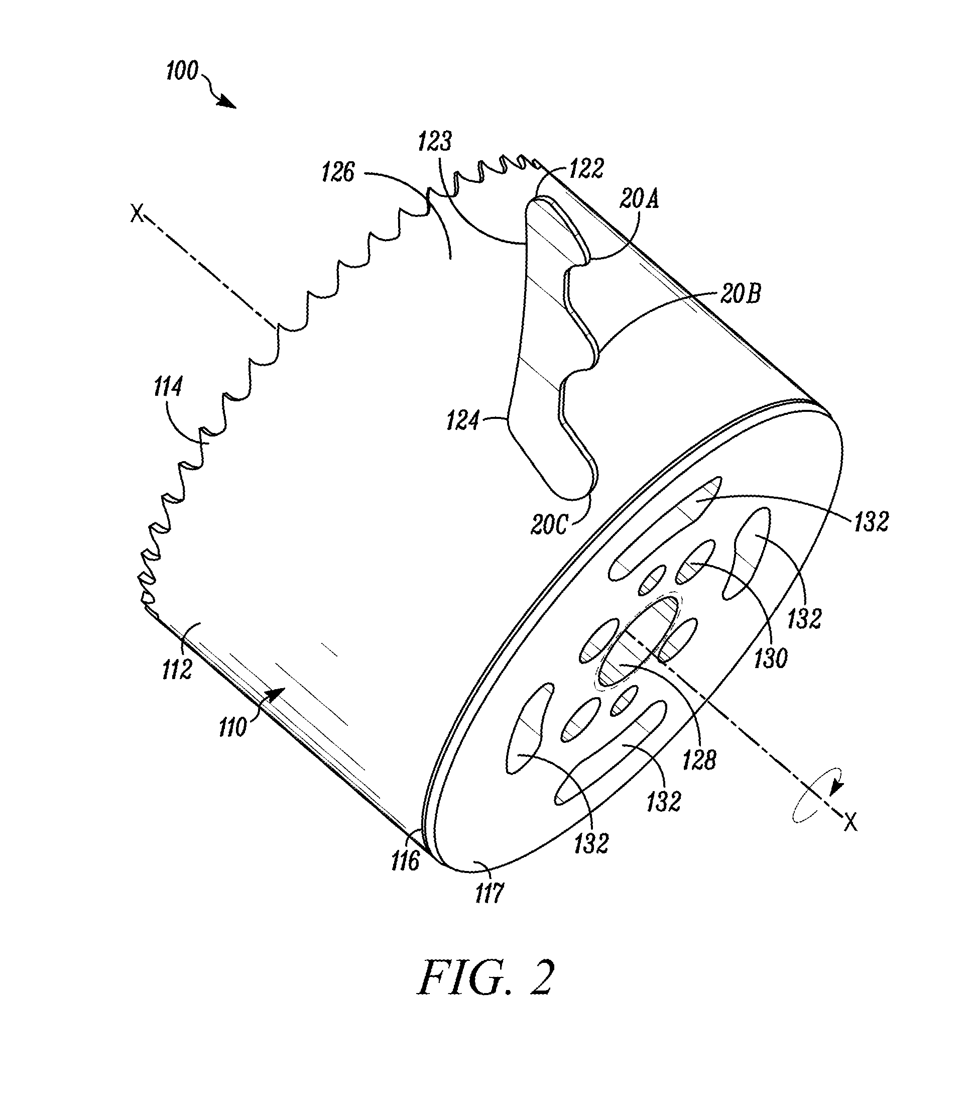
[0023]In FIG. 1, a blade body of a hole cutter embodying the present invention is indicated generally by the reference numeral 10. The term “hole cutter” is used here to mean a tool that cuts holes in work pieces, such as wood or metal work pieces, and includes without limitation hole saws. The blade body 10 is shown in FIG. 1 in its flattened state; however, as will be recognized by those of ordinary skill in the pertinent art based on the teachings herein, the blade body 10 is rolled or otherwise formed into a substantially cylindrical shape to form the hole cutter. The blade body 10 comprises a side wall 12 that extends around an axis of rotation “X” of the hole cutter to define a substantially cylindrical blade body. One end of the blade body is provided with a cutting edge 14 oriented substantially perpendicular to the axis of rotation X, and the opposing end of the blade body defines a rim 16. A cap (not shown) is fixedly secured to the rim 16 to enclose the respective end of ...


PUM

PropertyMeasurementUnit
Timeaaaaaaaaaa
Thicknessaaaaaaaaaa
Thicknessaaaaaaaaaa

Abstract

A hole cutter has a cylindrical blade body including a cutting edge and one or more axially-elongated apertures formed within a side wall of the blade body. The axially-elongated aperture is configured to receive a lever, such as a screwdriver, therethrough. Each axially-elongated aperture includes a first fulcrum axially spaced adjacent to the cutting edge, a second fulcrum axially spaced further away from the cutting edge than the first fulcrum, and optionally a third fulcrum axially spaced between the first and second fulcrums. A lever, such as a screwdriver, can be inserted into the aperture and placed against each of the fulcrums to lever slugs out of the interior of the blade body.

Description

[0001]This application is a continuation-in-part of co-pending U.S. patent application Ser. No. 12 / 687,065 filed Jan. 13, 2010, the disclosure of which is incorporated by reference as if set forth herein in its entirety.FIELD OF THE INVENTION[0002]The present invention relates to hole cutters, and more particularly, to hole cutters with apertures in their side walls that define fulcrums for inserting and levering a tool, such as a screwdriver, to remove work piece slugs from the interiors of the hole cutters.BACKGROUND[0003]A hole cutter, or hole saw, is a type of cutter used in drilling circular holes in various materials, such as wood, metal, drywall, etc. A hole cutter typically has a substantially cylindrical body that defines a side wall, a circular cutting edge with teeth located at one end of the body and designed to cut a work piece during rotation of the cutter, and a cap located at the end of the body opposite the cutting edge. The cap typically includes threads, holes or ...

Claims


Application Information

Patent Timeline
IPC IPC(8): B23B51/04
CPCB23B51/0453Y10T408/895B23B51/0406B23B51/04B23B51/0467
Inventor NOVAK, JOSEPH THOMASGREEN, MATTHEW CHRISTOPHER
Owner BLACK & DECKER INC
Why Eureka
Try Eureka