Fluid end assembly

a technology of end assembly and fluid, which is applied in the direction of pump components, positive displacement liquid engines, liquid fuel engine components, etc., can solve the problems of limiting the pressure rating of the reservoir, limiting the economic production of hydrocarbons from low-permeability reservoir rocks, and affecting the economic production of hydrocarbons, etc., to achieve long working life, easy replacement, and long service life

Inactive Publication Date: 2011-08-25
FORUM US
View PDF40 Cites 24 Cited by
  • Summary
  • Abstract
  • Description
  • Claims
  • Application Information

AI Technical Summary

Benefits of technology

[0005]In light of the problems associated with the known fluid ends used in high-pressure pumps that are prone to fatigue failures, it is a principal object of the invention to provide a fluid end assembly having a Y-type configuration that is extremely durable and has a long working life. Worn parts of my fluid end assembly can easily be replaced.

Problems solved by technology

It is difficult to economically produce hydrocarbons from low permeability reservoir rocks.
It is the connections between the parts and the supporting features for the valves that tend to weaken a fluid end, limiting its pressure rating, and making it susceptible to corrosion, leaks, and cracks under high, cyclical stresses.
Thus, fluid ends sometimes fail under load prematurely.
Few of the proposed Y-type designs have seen widespread use or commercial success since they have been difficult and costly to make and equally difficult to service in the field.

Method used


Image

  • Fluid end assembly
  • Fluid end assembly
  • Fluid end assembly

Examples


first embodiment

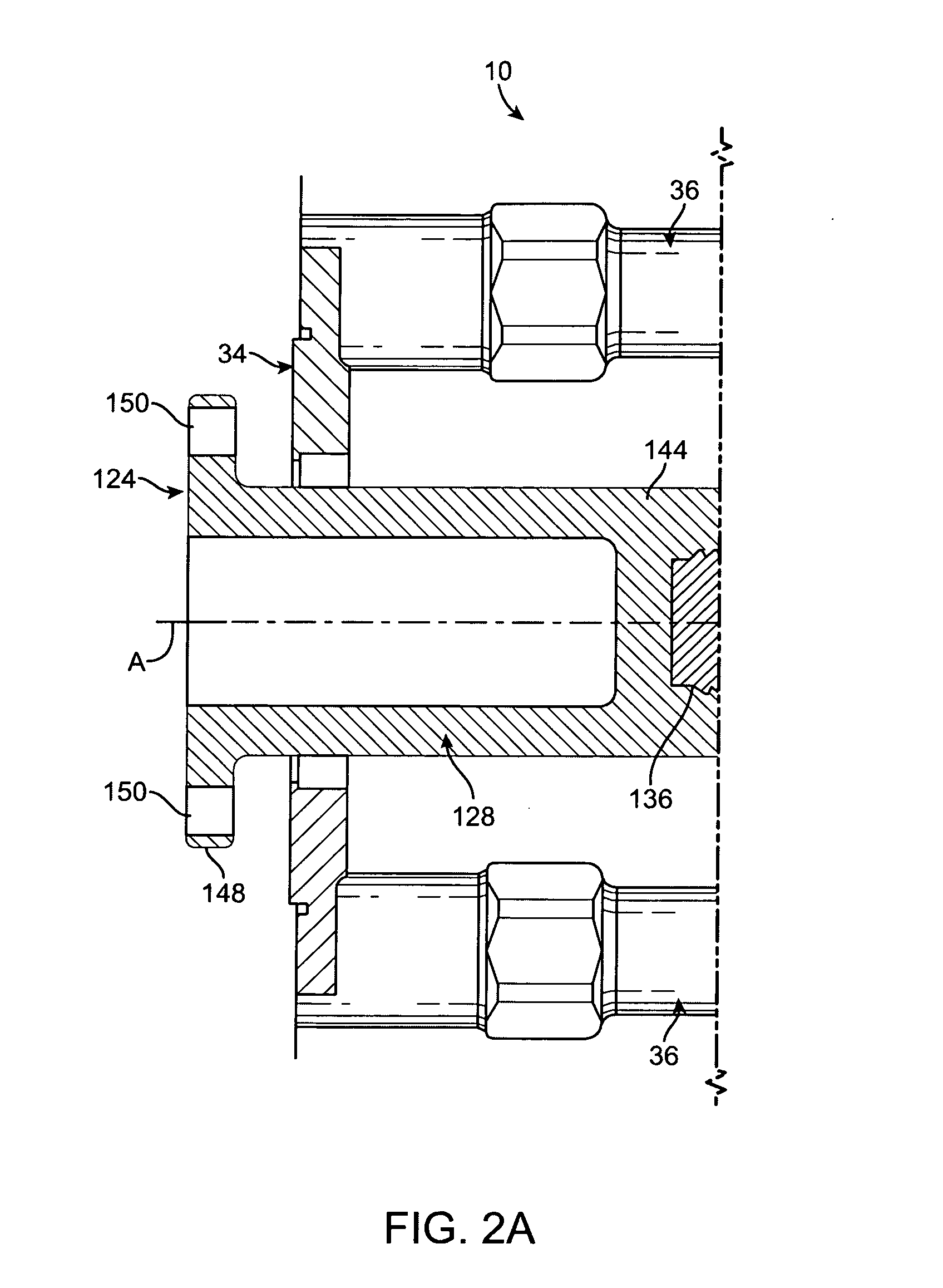
[0026]Referring now to FIGS. 1 and 2 of the drawings, my fluid end assembly is shown at 10. Fluid end assembly 10 includes a pump housing 12 having a plunger bore 14 within which a plunger 16 reciprocates. At its inner end, plunger bore 14 terminates in a pumping chamber 18 that is supplied with fluid from above by a suction passage 20 in pump housing 12. Fluid pressurized by plunger 16 exits pumping chamber 18 downwardly through a discharge passage 22 in pump housing 12. A suction valve 24 in suction passage 20 establishes the one-way flow of fluid from a supply manifold 28 into pumping chamber 18. A discharge valve 26 in discharge passage 22 sets up the one-way flow of fluid from pumping chamber 18 into an outlet passage 30 for release from fluid end assembly 10.

[0027]Pump housing 12 is a steel block of suitable size and shape. To lower its weight and increase its strength, housing 12 is provided with a plunger section 32 of reduced height that contains the outer end of plunger bo...

second embodiment

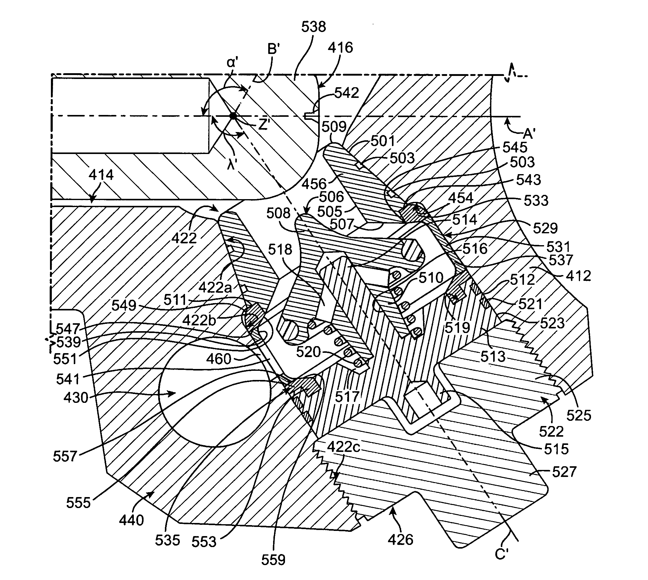
[0045]Referring now to FIGS. 3 and 4 of the drawings, my fluid end assembly is shown at 410. Fluid end assembly 410 is substantially the same as fluid end assembly 10 except that a suction valve 424 and a discharge valve 426, and the passages 420 and 422 for the valves 424 and 426, have been modified somewhat. These modifications are believed to further strengthen valves 424 and 424 and fluid end assembly 410.

[0046]Fluid end assembly 410 includes a pump housing 412 having a plunger bore 414 within which a plunger 416 reciprocates. At its inner end, plunger bore 414 terminates in a pumping chamber 418 that is supplied with fluid by a suction passage 420 in pump housing 412. Fluid pressurized by plunger 416 exits pumping chamber 418 through a discharge passage 422 in pump housing 412 located opposite suction passage 420. A suction valve 424 in suction passage 420 permits the one-way flow of fluid from a supply manifold 428 to pumping chamber 418. A discharge valve 426 in discharge pas...


PUM


Abstract

A fluid end assembly including a pump housing with a number of interior passages for the flow of fluids. The housing has a plunger bore with a closed inner end and an open outer end. A suction passage intersects the plunger bore. A discharge passage intersects both the plunger bore and the suction passage such that the discharge passage, the suction passage, and the plunger bore radiate outwardly from their point of intersection to define a shape resembling a “Y”. A connector passage branches from the discharge passage. An outlet passage intersects the connector passage and passes through the pump housing at right angles to the plunger bore. A reciprocating plunger is located in the plunger bore. A suction valve is located in the suction passage. A discharge valve is located in the discharge passage. A fluid supply manifold is pivotally secured to the housing and is in fluid communication with the suction passage.

Description

FIELD OF THE INVENTION[0001]The invention relates generally to pumps having pumping chamber pressure-responsive fluid distributors and, more particularly, to such pumps having distributors positioned opposite the end face of a pumping member.BACKGROUND OF THE INVENTION[0002]It is difficult to economically produce hydrocarbons from low permeability reservoir rocks. Oil and gas production rates are often boosted by hydraulic fracturing, a technique that increases rock permeability by opening channels through which hydrocarbons can flow to recovery wells. During hydraulic fracturing, a fluid is pumped into the earth under high pressure (sometimes as high as 50,000 PSI) where it enters a reservoir rock and cracks or fractures it. Large quantities of proppants are carried in suspension by the fluid into the fractures. When the pressure is released, the fractures partially close on the proppants, leaving channels for oil and gas to flow.[0003]Specialized pumps are used to deliver fracture...

Claims


Application Information

Patent Timeline
Patent Type & Authority Applications(United States)
IPC IPC(8): F04B53/10F04B53/00
CPCF04B53/007
Inventor VICARS, BERTON L.
Owner FORUM US
Why Eureka
Try Eureka