Scan driver and organic light emitting display using the scan driver

a scan driver and scan line technology, applied in the direction of digital storage, instruments, computing, etc., can solve the problems of irregular or degraded image, increase the rc delay of a scan signal transmitted on such scan lines, etc., and achieve the effect of preventing or reducing the generation of abnormal scan signals

Active Publication Date: 2011-09-22
SAMSUNG DISPLAY CO LTD
View PDF11 Cites 25 Cited by
  • Summary
  • Abstract
  • Description
  • Claims
  • Application Information

AI Technical Summary

Benefits of technology

[0009]Embodiments of the present invention are directed toward a scan driver which may prevent or reduce generation of an abnormal scan signal and provide a regular image, and an organic light emitting display using the scan driver.

Problems solved by technology

As a load of the scan line increases, RC delay of a signal transmitted on such scan line increases.
Also, when the scan time is shortened in a compensation pixel circuit, a compensation time is shortened accordingly so that normal compensation may not be performed which causes an irregular or degraded image.

Method used


Image

  • Scan driver and organic light emitting display using the scan driver
  • Scan driver and organic light emitting display using the scan driver
  • Scan driver and organic light emitting display using the scan driver

Examples


Embodiment Construction

[0026]The attached drawings for illustrating exemplary embodiments of the present invention are referred to in order to gain a sufficient understanding of the present invention, the merits thereof, and the features and aspects of the present invention. Hereinafter, the present invention will be described in detail by explaining exemplary embodiments of the invention with reference to the attached drawings. Here, when a first element is described as being coupled or connected to a second element, the first element may be directly coupled to the second element or indirectly coupled to the second element via a third element. Like reference numerals in the drawings denote like elements.

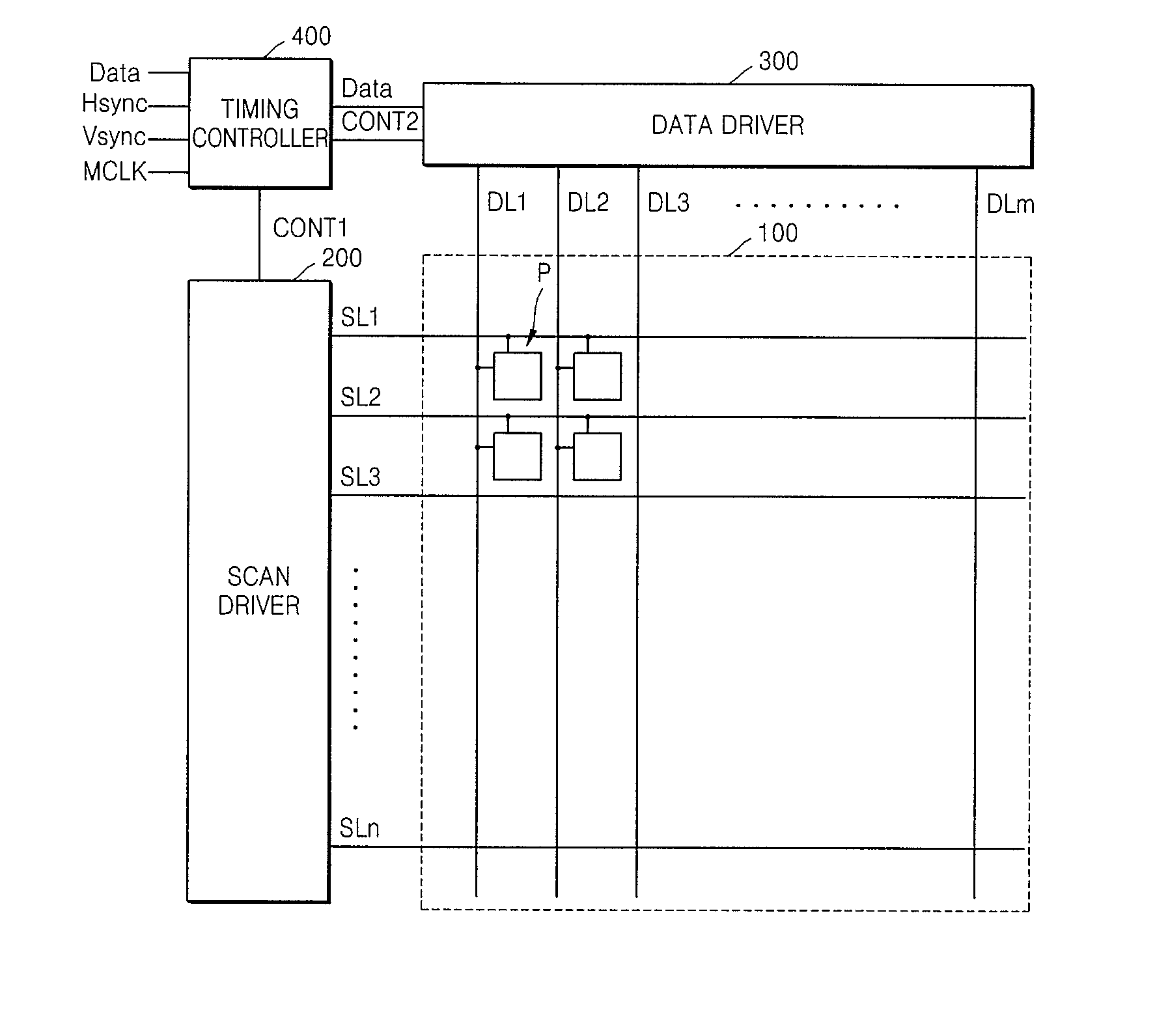
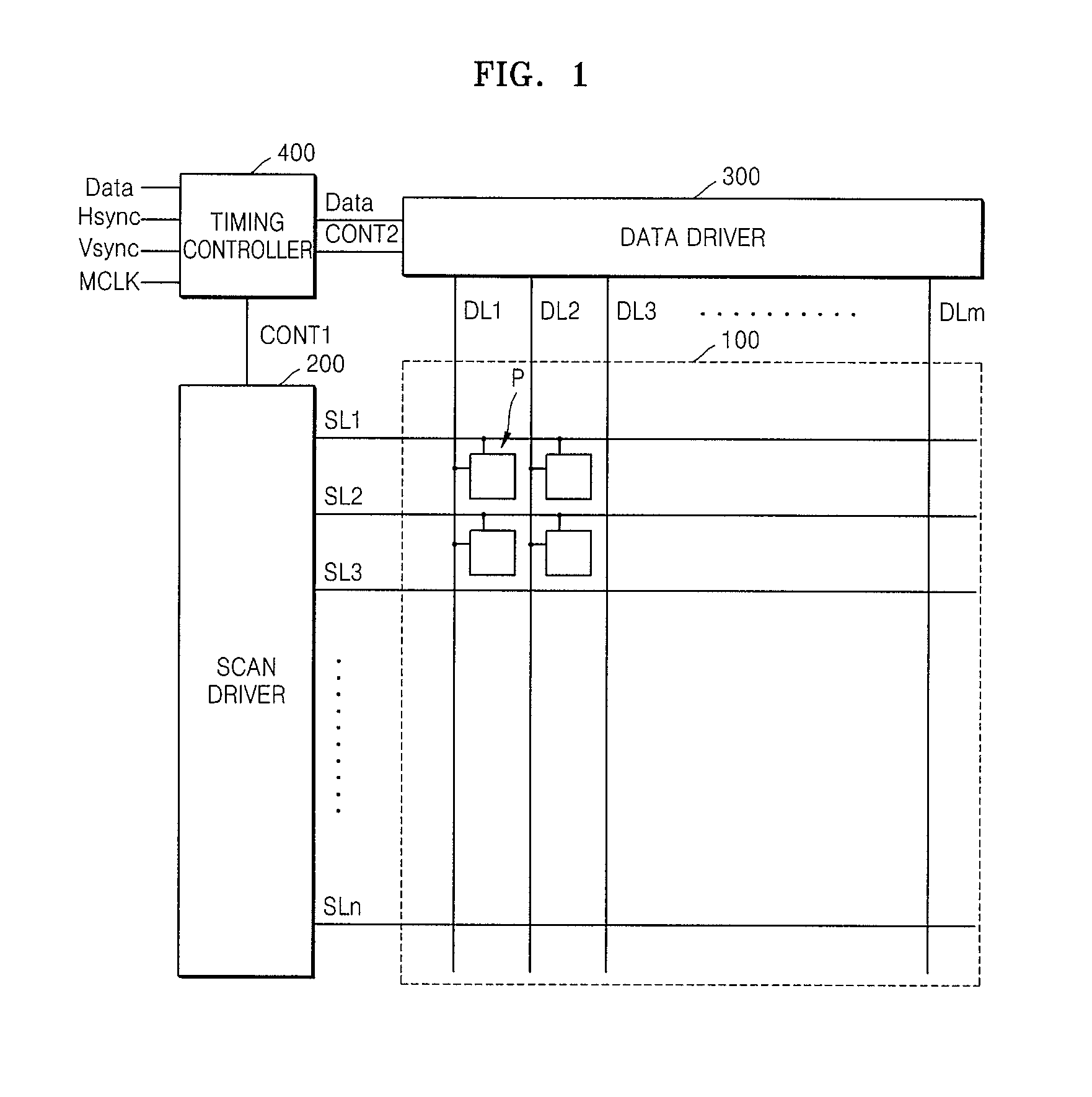
[0027]FIG. 1 is a circuit diagram schematically showing the structure of an organic light emitting display according to an embodiment of the present invention. Referring to FIG. 1, the organic light emitting display includes an organic light emitting panel 100, a scan driver 200, a data driver 300, and a ...


PUM


Abstract

A scan driver is coupled to a plurality of scan lines and includes a plurality of stages. Each of the stages is configured to sequentially receives clock signals that are phase delayed by two horizontal cycles or more from three of a plurality of clock lines, and output a scan signal having a pulse width of two horizontal cycles or more to a corresponding scan line. The scan signals are overlapped with each other by one horizontal cycle or more.

Description

CROSS-REFERENCE TO RELATED PATENT APPLICATIONS[0001]This application claims priority to and the benefit of Korean Patent Application No. 10-2010-0023401, filed on Mar. 16, 2010, in the Korean Intellectual Property Office, the disclosure of which is incorporated herein in its entirety by reference.BACKGROUND[0002]1. Field[0003]Aspects of embodiments of the present invention relate to a scan driver and an organic light emitting display using the scan driver.[0004]2. Description of the Related Art[0005]Organic light emitting displays may be used as display devices for personal computers, mobile phones, and portable information terminals such as personal digital assistants (PDAs), or for a variety of information devices. Also, a variety of light emitting display devices having reduced weight and volume compared to cathode ray tube displays have been developed. For example, the organic light emitting display has superior light emission efficiency, brightness, viewing angle, and a fast re...

Claims


Application Information

Patent Timeline
Patent Type & Authority Applications(United States)
IPC IPC(8): G09G5/00
CPCG09G3/3266G11C19/184G09G2310/06G09G2310/0286G11C19/28
Inventor CHUNG, KYUNG-HOON
Owner SAMSUNG DISPLAY CO LTD
Why Eureka
Try Eureka