
Mask blank manufacturing method and sputtering target for manufacturing the same

a mask blank and manufacturing method technology, applied in the field of mask blank manufacturing methods and sputtering targets for manufacturing mask blanks, can solve the problems of krf excimer lasers that are not easy to manufacture, the requirement for reducing particles and pinholes is more severe, and the yield is also deteriorated, so as to prevent or reduce the generation of particles on the substrate, prevent or reduce the production of particles, and manufacture stably a mask blank

Active Publication Date: 2010-11-16
HOYA CORP
View PDF14 Cites 7 Cited by
  • Summary
  • Abstract
  • Description
  • Claims
  • Application Information

AI Technical Summary

Benefits of technology

This design effectively reduces the generation of particles on the substrate, allowing for stable and continuous production of mask blanks with reduced phase angle and transmittance variations, enhancing mass productivity for short-wavelength applications.

Problems solved by technology

In a mask blank for a short wavelength, for example, an ArF or F2 excimer laser, a variation in a phase angle and a transmittance between blanks or in a plane in a mask blank for conventional i rays and a KrF excimer laser is great and a yield is also deteriorated.
In reflection of the reduction of the exposure wavelength, furthermore, the requirement for reducing a particle and a pinhole becomes more severely.
As a result, however, there was a problem in that the particles with relatively large size (for example, a diameter of 300 nm or more) appear on the substrate.

Method used


Image

  • Mask blank manufacturing method and sputtering target for manufacturing the same
  • Mask blank manufacturing method and sputtering target for manufacturing the same
  • Mask blank manufacturing method and sputtering target for manufacturing the same

Examples


example

[0090]An example of the invention will be described below in more detail.

[0091]By using the DC magnetron sputtering apparatus described above with reference to FIGS. 7 to 9, 100 halftone contain phase shift mask blanks for an ArF excimer laser (193 nm) were fabricated one by one by continuously forming a film at a constant interval.

[0092]More specifically, a thin film (a thickness of approximately 670 angstroms) of molybdenum and silicon (MoSiN) nitrided on a transparent substrate (a quartz substrate of 6-inch square having a thickness of 0.25 inch) was formed through reactive sputtering (DC sputtering) in a mixed gas atmosphere (Ar: N2=10%:90%, a pressure: 0.1 Pa) of argon (Ar) and nitrogen (N2) by using a mixed target (Mo:Si=8:92 mol %) of molybdenum (Mo) and silicon (Si) so that a phase shift mask blank (a film composition of Mo:Si:N=7:45:48) for an ArF excimer laser (a wavelength of 193 nm) was obtained.

[0093]In the example, as shown in FIG. 7, there was used the apparatus havin...


PUM

PropertyMeasurementUnit
angleaaaaaaaaaa
diameteraaaaaaaaaa
melting pointaaaaaaaaaa

Abstract

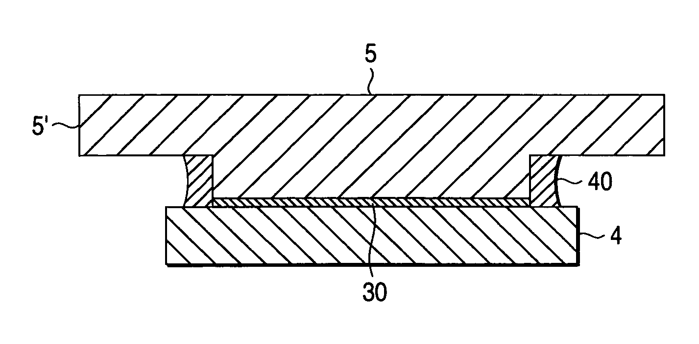
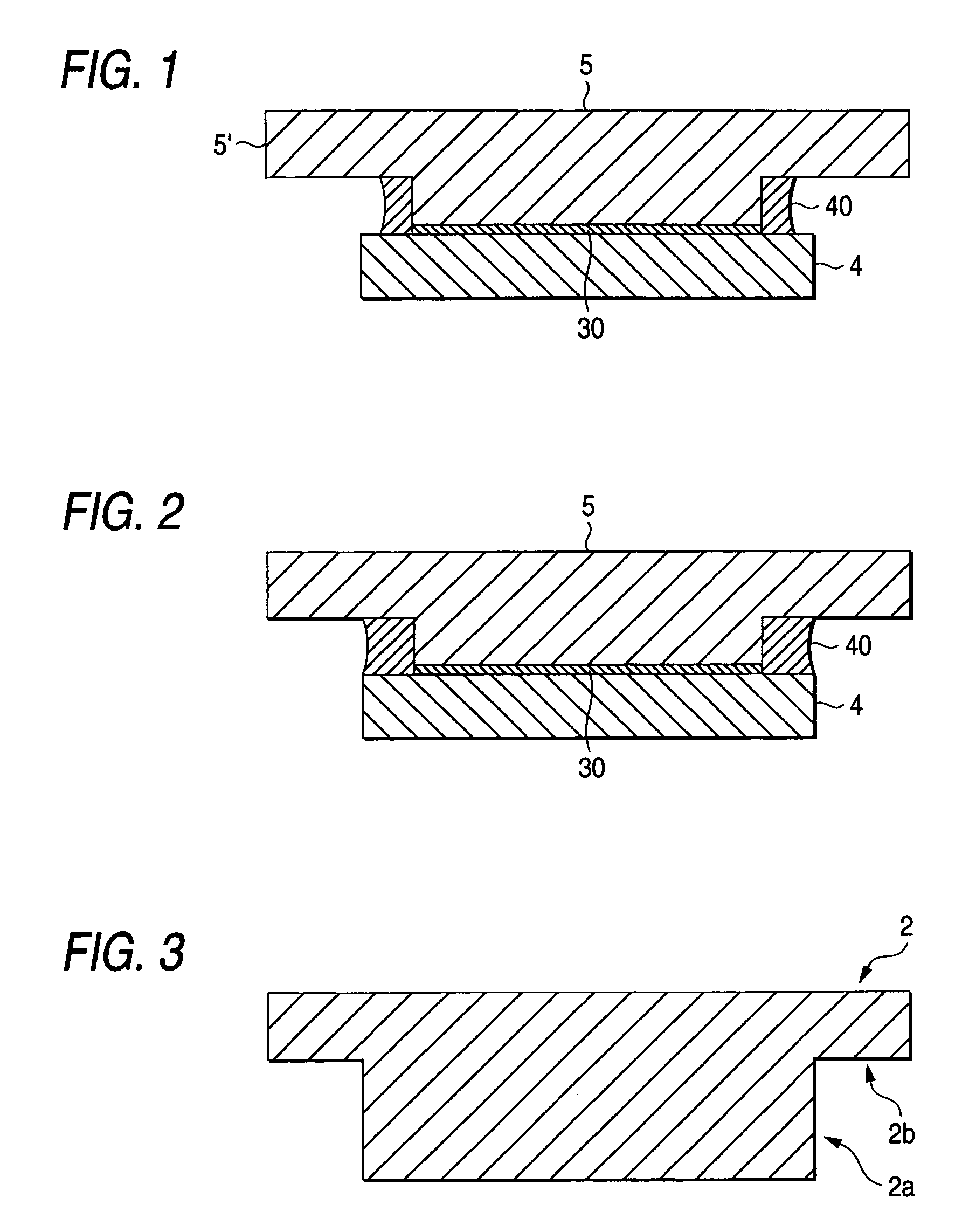
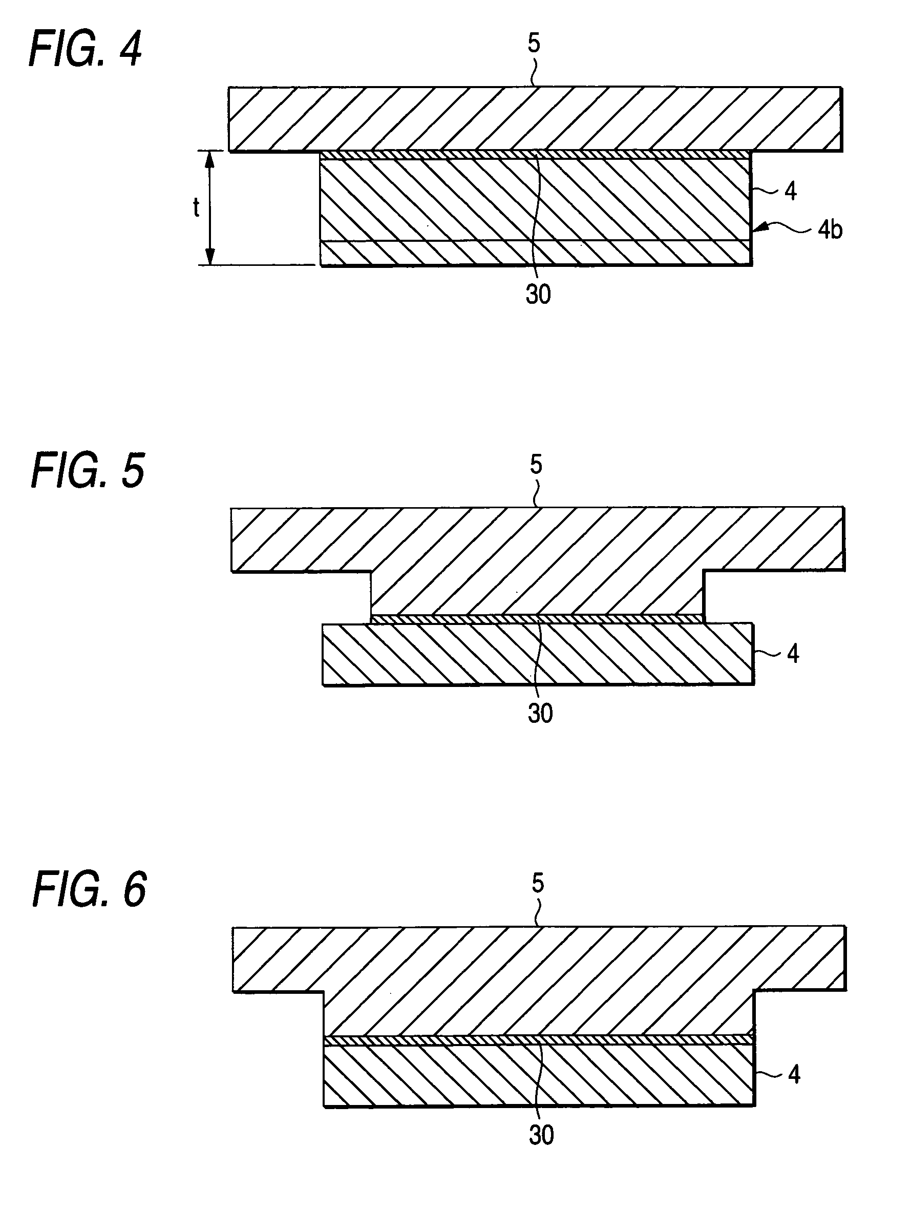
A sputtering target for manufacturing a mask blank having a backing plate 5 where a portion for bonding a target member 4 is protruded like the convex with respect to a base portion 5′, and the target member 4 being formed to have a larger surface area than the area of the bonding portion of the backing plate 5 with extending from the bonding portion over a whole periphery with a bonding agent 30 interposed in-between, and further a metal 40 is deposited to a concave portion formed by a combination of the two structures in such a manner that the elution of the bonding agent 30 can be sealed.

Description

[0001]This application claims priority based on Japanese Patent application No. 2004-002524, filed Jan. 7, 2004, the contents of which is incorporated herein by reference in its entirety.BACKGROUND OF THE INVENTION[0002]1. Field of the Invention[0003]The present invention relates to a method of manufacturing a mask blank and a sputtering target for manufacturing a mask blank.[0004]2. Description of the Related Art[0005]In recent years, a semiconductor device has been demanded to be processed more finely. For this reason, an exposure wavelength to be used has come to be shorter than before. With respect of such a short exposure wavelength, various technical requirements are demanded for realizing such a mask blank more severely.[0006]For example, a light translucent film (a halftone phase shift film) in a phase shift mask blank of a halftone type is employed to meet the demanded requirements from both aspects of a light transmittance and a phase shift amount for an exposure wavelengt...

Claims


Application Information

Patent Timeline
Patent Type & Authority Patents(United States)
IPC IPC(8): C23C14/35B32B9/00B32B17/06C23C14/00C23C14/06C23C14/22C23C14/32C23C14/34G03F1/50G03F1/68G03F9/00H01L21/027
CPCC23C14/0641C23C14/225G03F1/68G03F1/14C23C14/3407G03F1/32E04G5/14E04G5/16E04G25/04
Inventor MITSUI, MASARUSUZUKI, TOSHIYUKI
Owner HOYA CORP
Learn More