Accessory for a fan

a fan and accessory technology, applied in auxillary pretreatment, heating types, separation processes, etc., can solve the problems of inability to carry, time-consuming cleaning of bladed fans, etc., and achieve the effect of easy insertion or pulling, easy cleaning, and minimizing the volume of the filter

Inactive Publication Date: 2011-09-29
DYSON TECH LTD
View PDF106 Cites 25 Cited by
  • Summary
  • Abstract
  • Description
  • Claims
  • Application Information

AI Technical Summary

Benefits of technology

[0008]The accessory is preferably in the form of a disposable filter unit which can be replaced when, for example, the fan is assigned to a different patient, when the fan is moved with the patient from an isolation ward to a general ward, or when the filter has reached the end of a prescribed usage period. This can significantly reduce the costs associated with the use of the fan, as the frequency with which the fan may need to be taken off site for cleaning can be significantly reduced.
[0009]The accessory is particular suitable for use with a portable bladeless fan, such as the Dyson Air Multiplier™ fan, in which the fan comprises a base having an air inlet located in a side wall of the base, and an air outlet detachably connectable to the base. In this case, the accessory may be locatable over or around the base so that the filter is located upstream from the air inlet of the base to remove airborne particulates from the air flow generated by the fan before the air flow enters the base. However, the accessory can be used with any fan which generates an air flow of sufficient pressure that the air flow is not choked by the attachment of the accessory to the fan. For example, the accessory may be used with a fan which is arranged to generate an air flow with a static pressure of at least 150 Pa so that the air flow is not choked when the accessory is attached to the fan, and so in a second aspect the present invention provides an accessory for a fan for generating an air flow with a static pressure of at least 150 Pa, the accessory comprising a high energy particle arrester filter and attachment means for detachably attaching the accessory to the fan.
[0013]In a preferred embodiment the accessory is in the form of a sleeve which is locatable about the side wall of the base of the fan. Forming the accessory in the form of a sleeve can enable the accessory to be easily pushed or pulled over the fan as required.
[0014]The filter preferably has a surface area in the range from 0.5 to 1.5 m2 which is exposed to the air flow generated by the fan. To minimize the volume of the filter, the filter is preferably pleated to form a filter which is substantially annular in shape for surrounding an air inlet of the fan. In this case, the accessory may comprise two annular discs between which the filter is located. These discs can be easily wiped clean during use of the accessory. Each disc may comprise a raised rim extending towards the other disc for retaining the filter between the discs. The filter may be readily adhered to the discs during the construction of the accessory. The discs may together be considered to form at least part of a filter unit to which the filter is adhered during construction of the filter unit.
[0015]The accessory may comprise an outer cover comprising a plurality of apertures through which air enters the accessory. This outer cover can provide a first, relatively coarse filter of the accessory to prevent airborne objects such as insects or large particles of dust from coming into contact with the filter, and can prevent the filter from being contacted by a user, particularly during the attachment of the filter to the fan, and so prevent damage to the filter. The outer cover is preferably transparent to allow a user to see the amount of dust or debris which has been captured by the filter.
[0022]The attachment means may comprise means for connecting the accessory to the base, and means for connecting the accessory to the air outlet. The air outlet of the fan is preferably detachably connected to the base of the fan. The air outlet of the fan preferably comprises means for connecting the air outlet to the base, which is preferably substantially the same as the means for connecting the accessory to the base. Similarly, the base of the fan preferably comprises means for connecting the base to the air outlet, which is preferably substantially the same as the means for connecting the accessory to the air outlet. This can simplify the attachment of the accessory to the fan, as the technique for connecting the air outlet to the base is the same as that for connecting the accessory to the base, and for connecting the air outlet to the accessory.

Problems solved by technology

The cleaning of bladed fans can be time consuming for the employee, as the cage housing the blades of the fan needs to be disassembled before the blades of the fan can be cleaned.
This disassembly usually requires the use of a screw driver, which cannot be carried by a nurse on a hospital ward.
Often, it can be more convenient for the hospital to engage a specialist cleaning company to clean the fan off site, although this can be very expensive.

Method used


Image

  • Accessory for a fan
  • Accessory for a fan
  • Accessory for a fan

Examples


Embodiment Construction

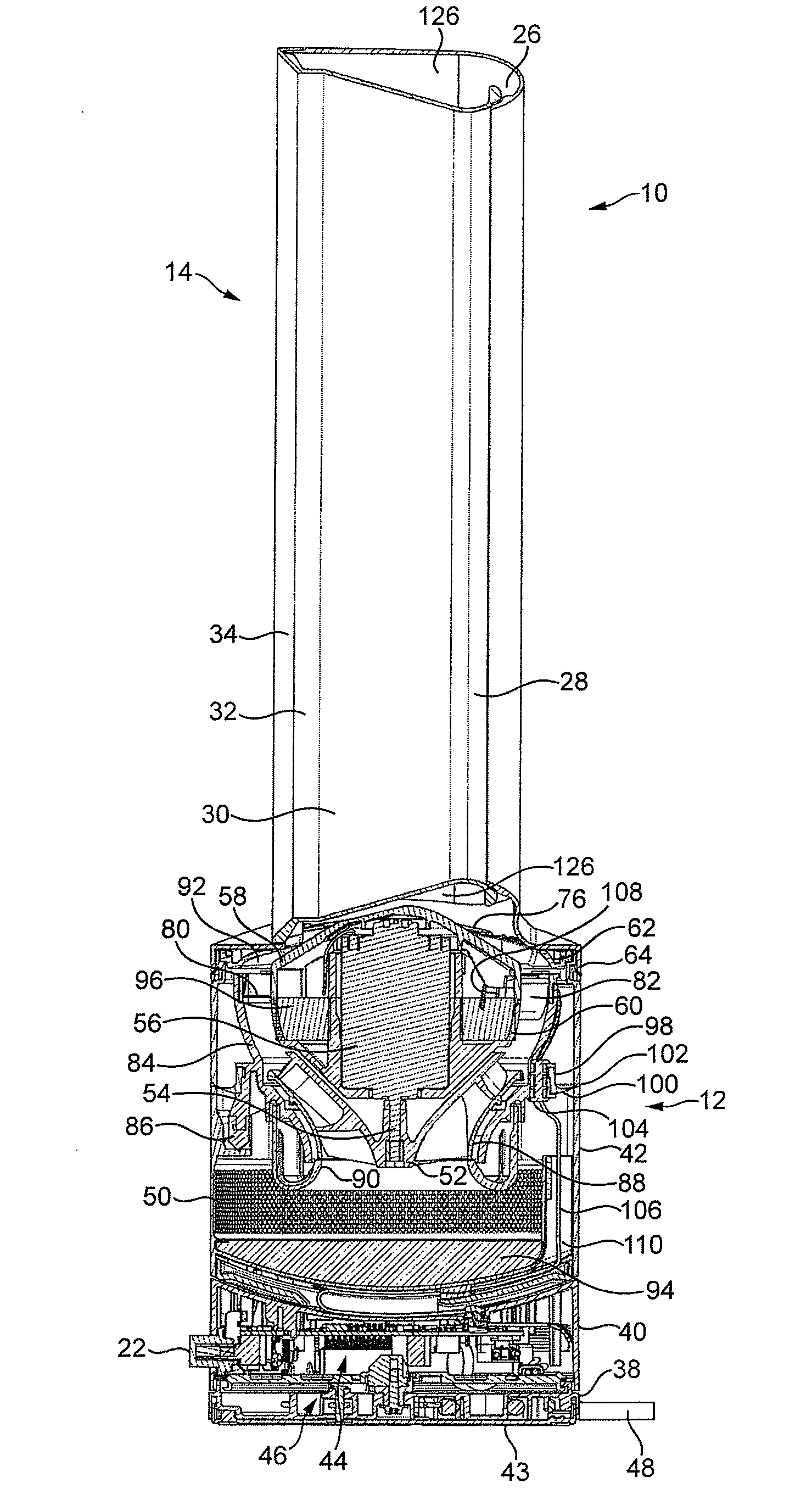
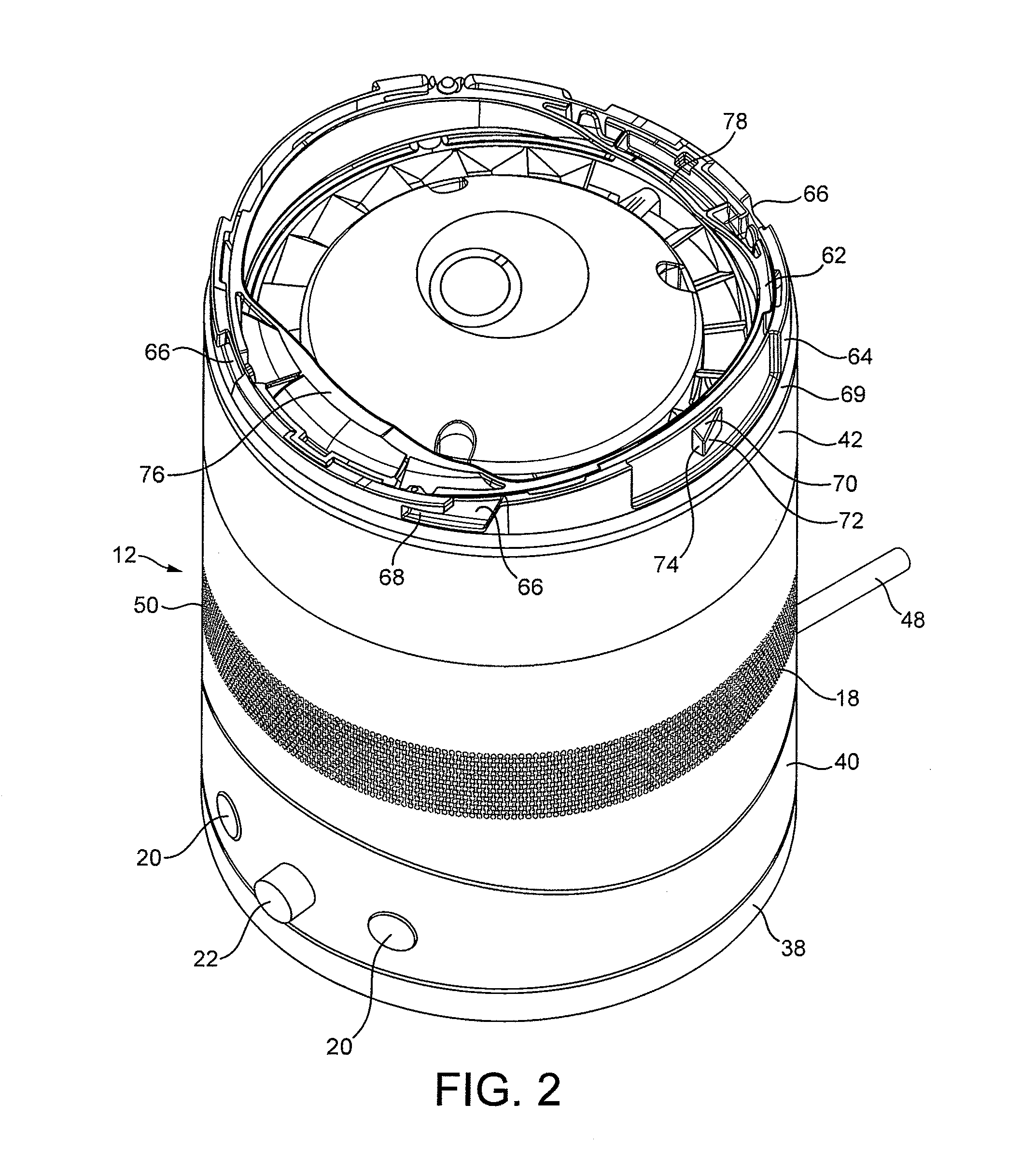
[0039]FIG. 1 is a front view of a fan 10. The fan 10 is preferably in the form of a bladeless fan 10 comprising a base 12 and an air outlet 14 connected to the base 12. With reference also to FIG. 2, the base 12 comprises a substantially cylindrical outer casing 16 having a plurality of air inlets 18 in the form of apertures formed in the outer casing 16 and through which a primary air flow is drawn into the base 12 from the external environment. The base 12 further comprises a plurality of user-operable buttons 20 and a user-operable dial 22 for controlling the operation of the fan 10. In this example the base 12 has a height in the range from 200 to 300 mm, and the outer casing 16 has an external diameter in the range from 100 to 200 mm.

[0040]As shown in FIG. 3, the air outlet 14 has an annular shape and defines an opening 24. The air outlet 14 has a height in the range from 200 to 400 mm. The air outlet 14 comprises a mouth 26 located towards the rear of the fan 10 for emitting a...


PUM

PropertyMeasurementUnit
static pressureaaaaaaaaaa
surface areaaaaaaaaaaa

Abstract

An external accessory for a portable fan including a base having an air inlet located in a side wall of the base, and an air outlet detachably connectable to the base, the accessory including a high energy particle arrester filter and connectors for detachably connecting the accessory to the fan so that the filter is located upstream from the air inlet of the fan.

Description

REFERENCE TO RELATED APPLICATIONS[0001]This application claims the priority of United Kingdom Application No. 1004812.2 filed Mar. 23, 2010, the entire contents of which are incorporated herein by reference.FIELD OF THE INVENTION[0002]The present invention relates to an accessory for a fan. Particularly, but not exclusively, the present invention relates to an accessory for a floor or table-top fan, such as a desk, tower or pedestal fan.BACKGROUND OF THE INVENTION[0003]A conventional domestic fan typically includes a set of blades or vanes mounted for rotation about an axis, and drive apparatus for rotating the set of blades to generate an air flow. The movement and circulation of the air flow creates a ‘wind chill’ or breeze and, as a result, the user experiences a cooling effect as heat is dissipated through convection and evaporation. The blades are generally located within a cage which allows an air flow to pass through the housing while preventing users from coming into contact...

Claims


Application Information

Patent Timeline
Patent Type & Authority Applications(United States)
IPC IPC(8): F04B53/20B01D46/42
CPCF04F5/16F04D29/703F04D25/08F05D2260/33F24F1/022F24F1/04F24F13/28
Inventor FITTON, NICHOLAS GERALDSIMMONDS, KEVIN JOHN
Owner DYSON TECH LTD
Why Eureka
Try Eureka