Retaining and Isolating Mechanisms for Magnets in a Magnetic Cleaning Tool

a technology of magnet retaining and isolating mechanism, which is applied in the direction of cleaning hollow articles, drilling pipes, drilling/well accessories, etc., can solve the problem of difficult removal from the mandrel

Active Publication Date: 2011-11-24
BAKER HUGHES INC
View PDF5 Cites 4 Cited by
  • Summary
  • Abstract
  • Description
  • Claims
  • Application Information

AI Technical Summary

Benefits of technology

[0006]The invention provides magnetic retrieval tools for use in a wellbore or other tubular member to remove metallic debris. In preferred embodiments, a retrieval apparatus includes a tool mandrel with insert pockets. In addition, the tool mandrel preferably includes a central collar with keyed openings. The retrieval appa...

Problems solved by technology

These devices and methods ensure that the magnets are not retained so close to the ma...

Method used


Image

  • Retaining and Isolating Mechanisms for Magnets in a Magnetic Cleaning Tool
  • Retaining and Isolating Mechanisms for Magnets in a Magnetic Cleaning Tool
  • Retaining and Isolating Mechanisms for Magnets in a Magnetic Cleaning Tool

Examples


Embodiment Construction

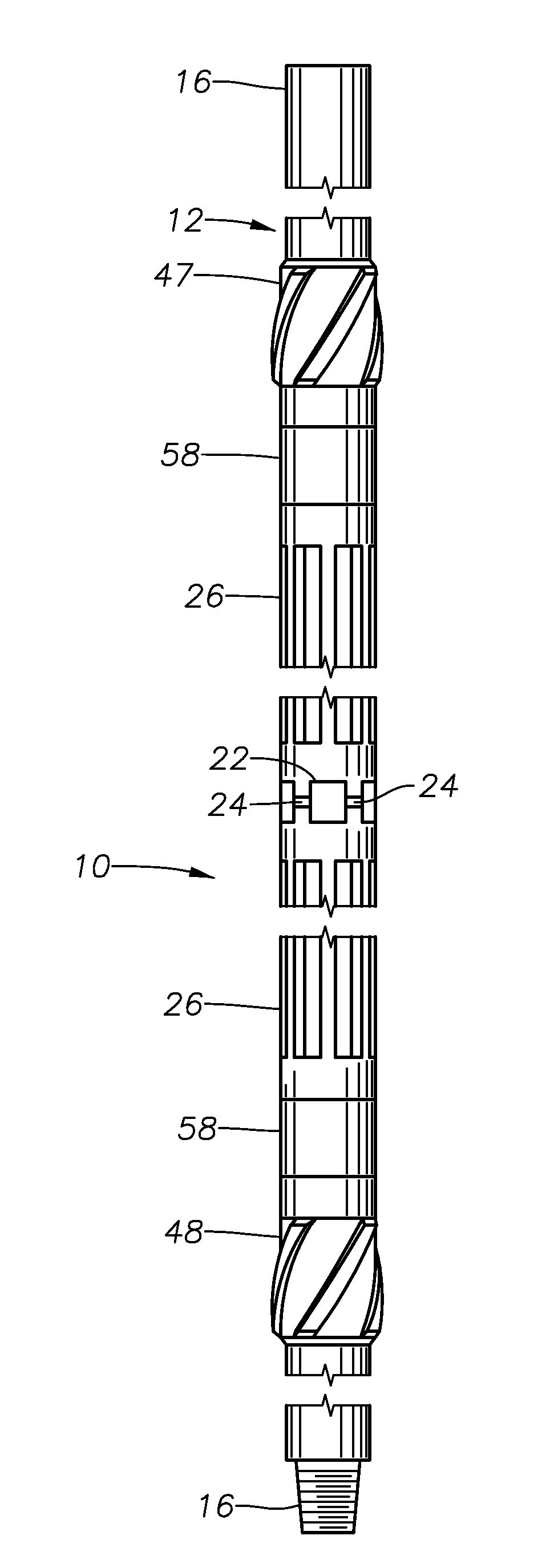
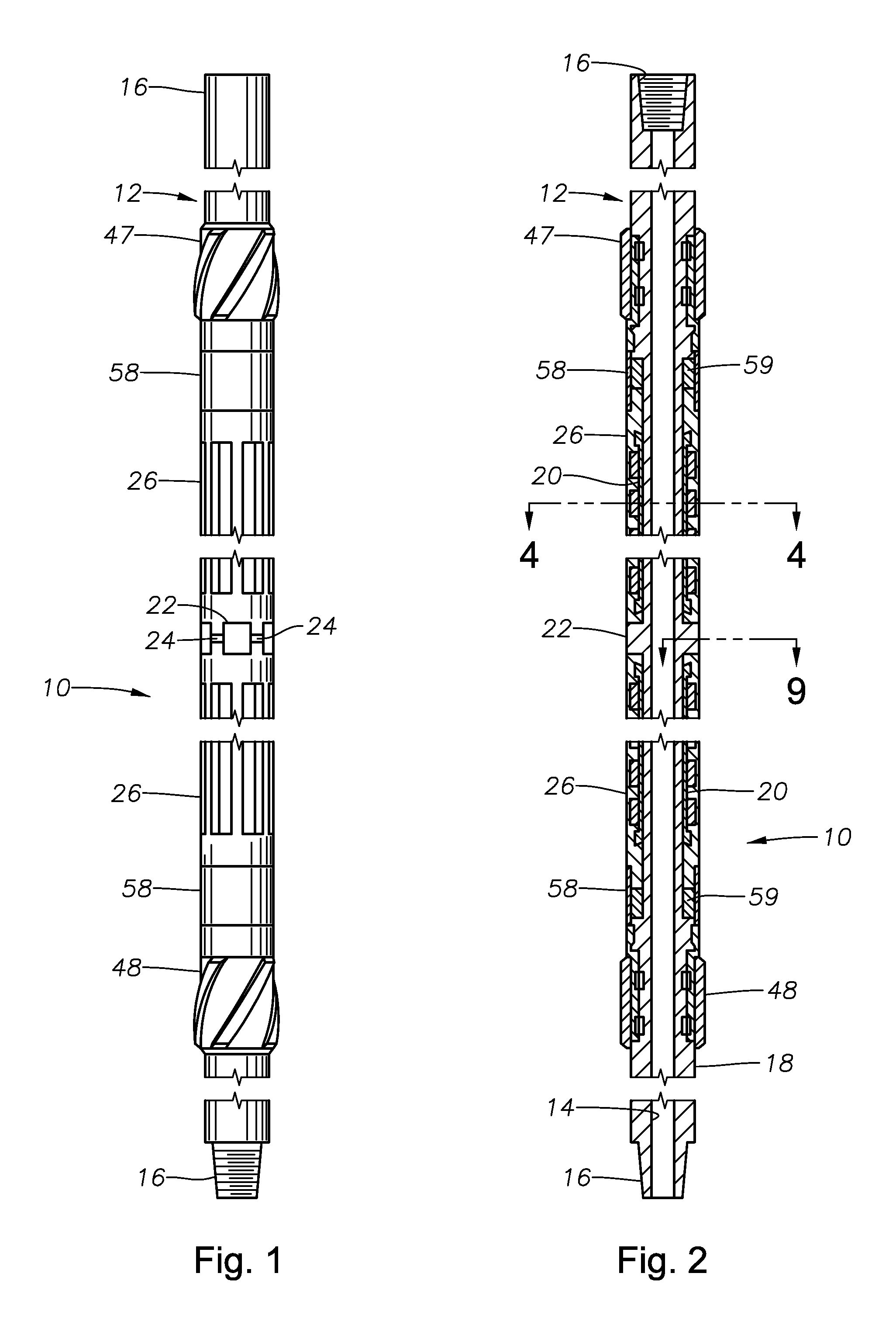
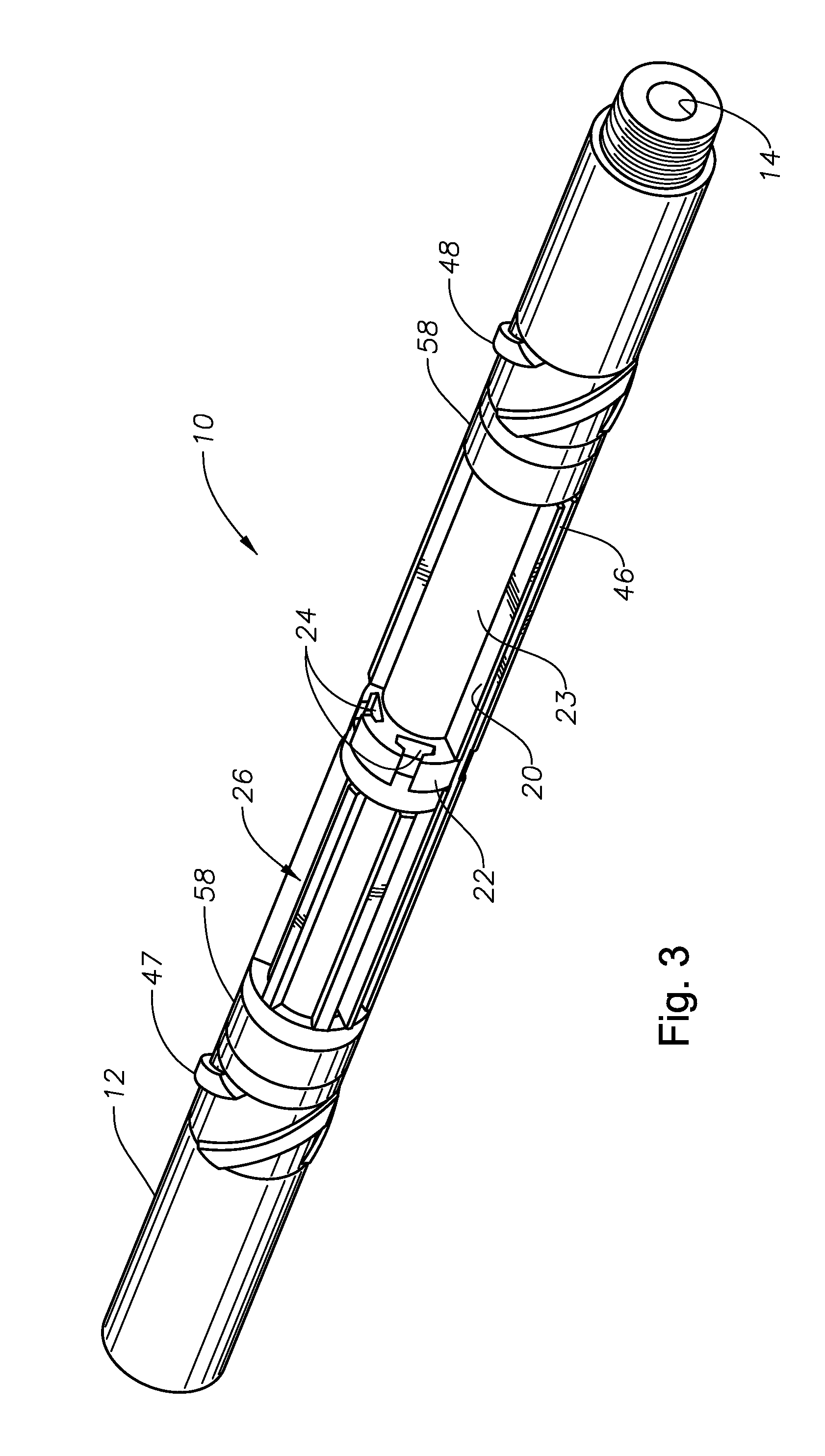
[0034]FIGS. 1-8 and 9 illustrate a first exemplary magnetic retrieval tool 10 that is constructed in accordance with the present invention. The tool 10 includes a cylindrical tool mandrel 12 which defines a central flowbore 14 (see FIG. 2) along its length. The tool mandrel 12 is provided with threaded connections 16 at its axial ends to permit the tool 10 to be incorporated into a downhole work string.

[0035]The tool mandrel 12 presents an outer radial surface 18 with a plurality of recessed pockets 20 formed therewithin. In the depicted embodiment, there are four pockets 20. Each of the pockets 20 is preferably axially elongated and arcuately curved, as shown in FIG. 3, wherein an empty pocket 20 is shown. In the depicted embodiment, each pocket 20 is located on the opposite side of the mandrel 12 from another pocket 20. In this embodiment, the pockets 20 provide an essentially semi-circular opening. The tool mandrel 12 also presents a radially-enlarged collar 22 which projects rad...


PUM


Abstract

A magnetic retrieval tool used for collecting metallic debris and material from within a wellbore or other surrounding downhole tubular. The tool includes a tool mandrel. A removable insert resides upon the tool mandrel. The insert retains a plurality of individual magnets in a fixed array or matrix surrounding the mandrel.

Description

BACKGROUND OF THE INVENTION[0001]1. Field of the Invention[0002]The invention relates generally to systems and methods for cleaning the interior of tubular members. In particular aspects, the invention relates to methods and devices for removing metallic debris from tubular members using magnets. In still other particular aspects, the invention relates to devices and methods for retaining a plurality of magnets within one or more housings that surround a mandrel and magnetically separating or isolating the magnets from the mandrel.[0003]2. Description of the Related Art[0004]Metallic debris accumulates within wellbores and other tubular members during production of subterranean fluids, such as hydrocarbon fluids. This metallic debris typically includes tiny metal shavings and cuttings. These shavings and cuttings result from numerous frictional operations that might occur within the wellbore or tubular, including the cutting of sidetracking windows, milling, drilling through of stuc...

Claims


Application Information

Patent Timeline
IPC IPC(8): E21B31/06
CPCE21B17/1078E21B37/00E21B31/06B08B9/0436E21B21/065
Inventor HERN, GREGORY L.PALMER, LARRY T.NELSON, JONATHAN F.
Owner BAKER HUGHES INC
Why Eureka
Try Eureka