Detactable Handle For Cookware

a technology for cookingware and handles, applied in the field of cookingware, can solve the problems of occupying space, difficult to place cookware in the dishwasher, camping cookware is designed, etc., and achieves the effects of less space, easy and quick attachment, and convenient and quick removal

Inactive Publication Date: 2012-07-05
DOYLE MICHAEL
View PDF0 Cites 6 Cited by
  • Summary
  • Abstract
  • Description
  • Claims
  • Application Information

AI Technical Summary

Benefits of technology

[0008]The invention is a handle that is easily and quickly attachable to and removable from cookware, such as a skillet or saucepan. The handle has a quick-release mechanism and a coupling element that couples with a receiver on the cookware. The handle is sturdy and provides a secure means for lifting and maneuvering cookware. Pots and pans are easier to load into a dishwasher and take up less space when the handles are removed. Storing cookware in a cupboard is also easier and also allows better use of space, if the handles are removed. The detachable handle according to the invention allows the handle to be removed from the pot or pan for storage and cleaning purposes, yet couples securely with the cookware when attached.
[0009]The removable handle with the quick-release coupler is rugged and capable of withstanding high compression, tension, and torque loads, which makes it safe and reliable for use in supporting cookware that may be heavy and very hot.

Problems solved by technology

Handles on cookware, such as pots, pans, skillets, etc., make it difficult to place the cookware in a dishwasher and generally take up space when storing them.
Typically, camping cookware is designed to be lightweight and compact, is generally small, and is not constructed as rugged long-lasting cookware for conventional household use.
The concept of the hinged or detachable handles, as used in camping gear, is not suited for conventional household use, because it does not meet general standards for safety, reliability, and durability.

Method used


Image

  • Detactable Handle For Cookware
  • Detactable Handle For Cookware
  • Detactable Handle For Cookware

Examples


second embodiment

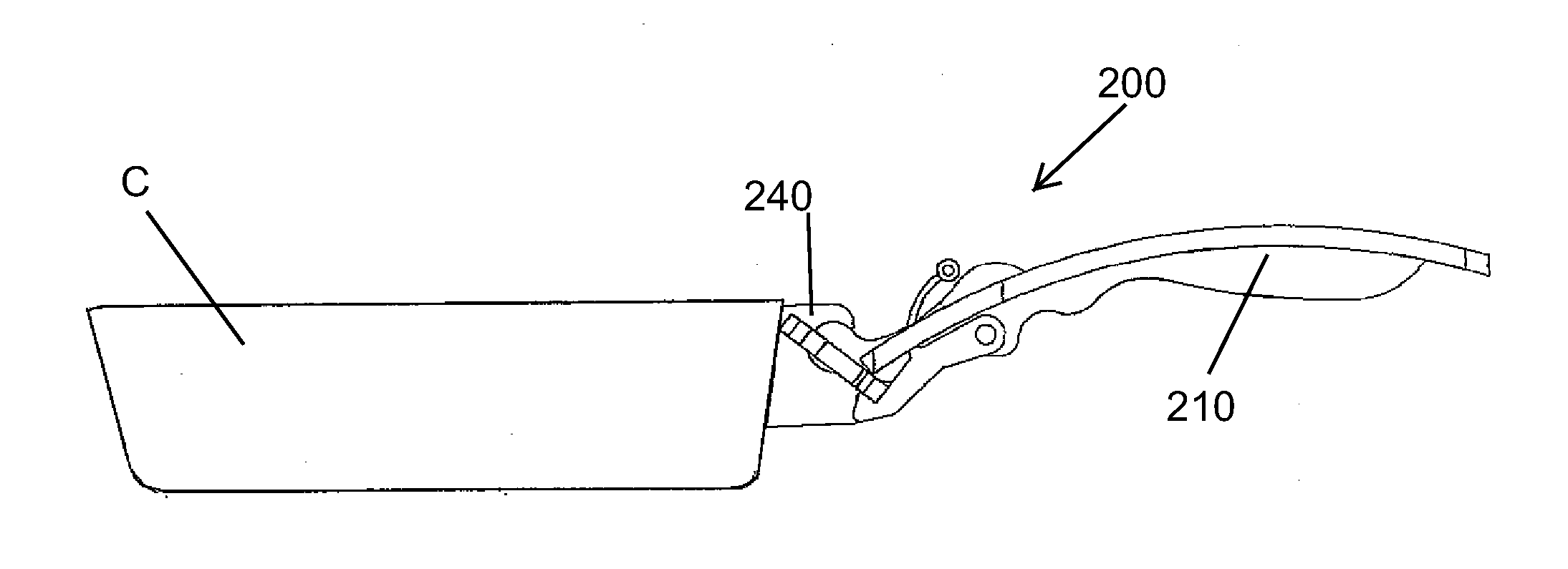
[0035]FIG. 14 is a schematic illustration of a detachable handle assembly 100 comprising a receiver component 10 and a handle 2 that has a detachable coupler 20 into which is incorporated a quick-release ball lock mechanism for coupling the handle 2 with the receiver component 10. The receiver component 10 is permanently and securely affixed to an article of cookware 1.

first embodiment

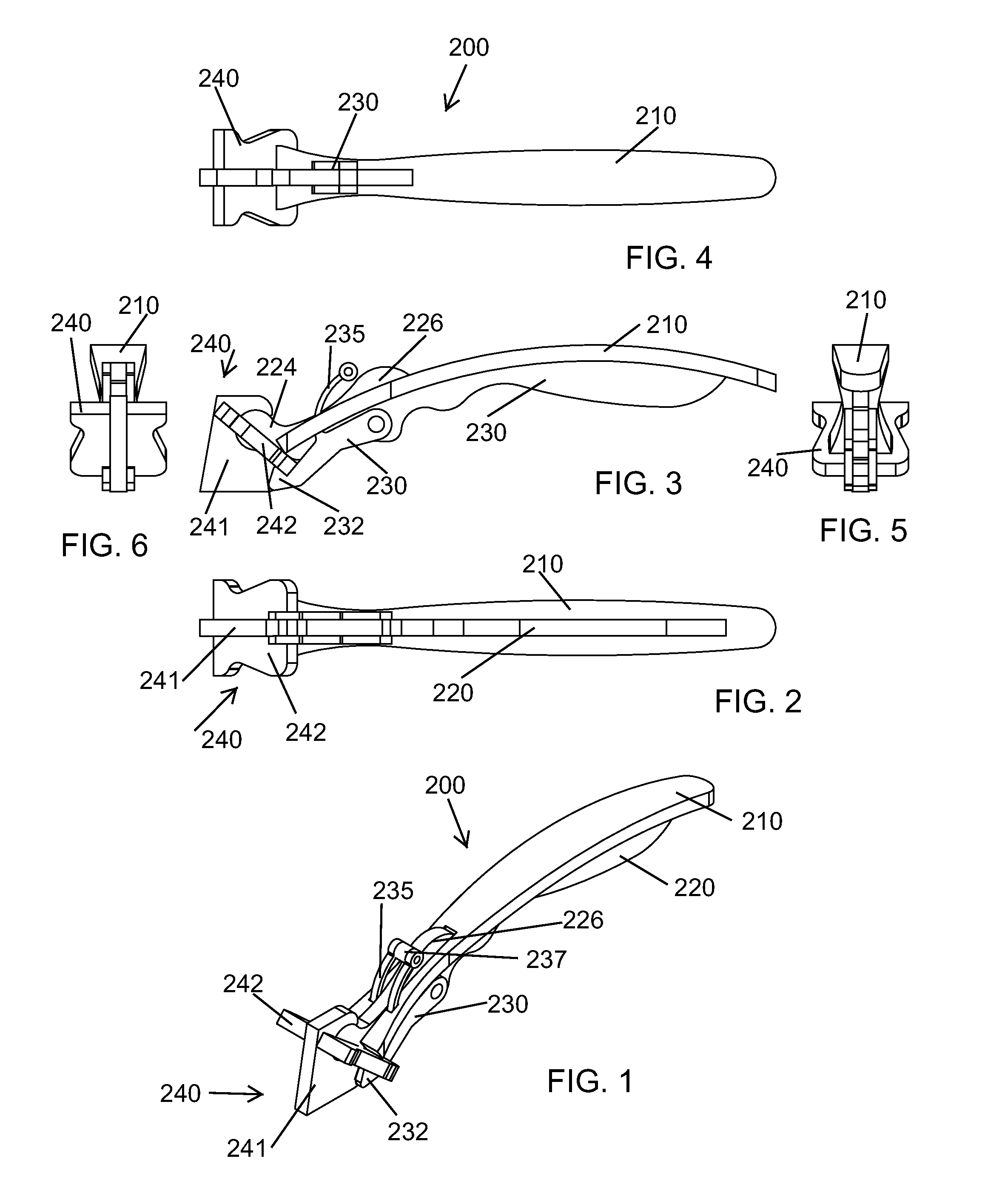
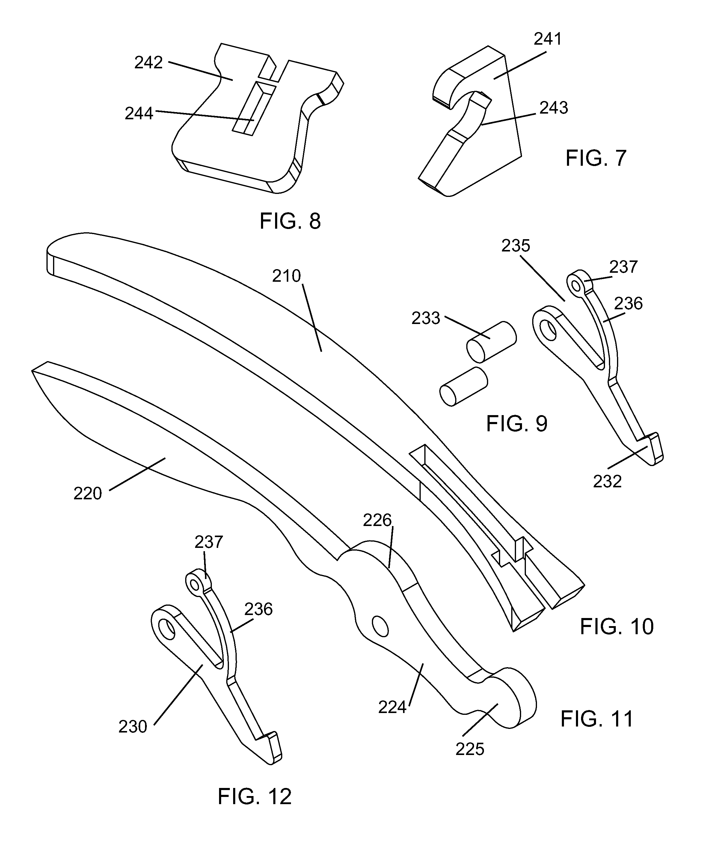
[0036]FIG. 15 illustrates details of the receiver component 10, which includes a mounting flange 12 and a receiver body 14. The receiver body 14 has an opening 16 that is contoured and sized to receive the detachable coupler 20. A groove or detent 18 for receiving a portion of the lock ball 28 is provided on at least one surface of the opening 16. In the embodiment shown in FIGS. 16 and 17, the groove 18 is shown on three side walls of the opening 16, but it is understood, that the groove 18 may be provided on just one surface or on two opposing surfaces. In the embodiment illustrated in FIG. 15, the coupler 20 is lowered into the receiver body 14 from above. This is a design choice. The handle may just as well be constructed such, that the coupler 20 is inserted into the receiver body 14 from below.

[0037]A brief description of the mechanism is provided here, with reference to the Wendling reference cited above, to provide an enabling disclosure of a suitable ball lock. The conventi...


PUM


Abstract

The invention is a handle that is detachable from cookware, to allow cookware to be stored more efficiently. The handle includes a handle receiver that is affixed to cookware and a handle with a coupling end that is insertable into the handle receiver. A locking mechanism automatically locks the handle into the handle receiver. The handle is detachable from the handle receiver by pushing on a release mechanism, which then allows the handle to be pulled away from the handle receiver.

Description

BACKGROUND INFORMATION[0001]1. Field of the Invention[0002]The invention relates to cookware. More particularly, the invention relates to a detachable handle for cookware.[0003]2. Discussion of Prior Art[0004]Handles on cookware, such as pots, pans, skillets, etc., make it difficult to place the cookware in a dishwasher and generally take up space when storing them. The handles are conventionally permanently affixed to the cookware.[0005]Some camping sets of cookware have a skillet or pots with a detachable or a hinged handle that folds over the cookware for compact storage. Typically, camping cookware is designed to be lightweight and compact, is generally small, and is not constructed as rugged long-lasting cookware for conventional household use. The concept of the hinged or detachable handles, as used in camping gear, is not suited for conventional household use, because it does not meet general standards for safety, reliability, and durability.[0006]Quick-release ball locks are...

Claims


Application Information

Patent Timeline
Patent Type & Authority Applications(United States)
IPC IPC(8): A47J45/07A47J45/10
CPCA47J45/07
Inventor DOYLE, MICHAEL
Owner DOYLE MICHAEL
Why Eureka
Try Eureka