Electric vehicle

a technology of electric vehicles and swing arms, applied in the direction of cycle equipment, transportation and packaging, cycle equipment, etc., can solve the problems of reduced operational efficiency, insufficient structure, and heavy load applied to only one side of the wheel, so as to achieve easy weight balance, improve the operational efficiency of mounting and removing the wheel and the motor, and increase the weight or stiffness of the swing arm.

Inactive Publication Date: 2012-10-04
HONDA MOTOR CO LTD
View PDF2 Cites 6 Cited by
  • Summary
  • Abstract
  • Description
  • Claims
  • Application Information

AI Technical Summary

Benefits of technology

[0028]Advantageous Effects of Invention include the following:
[0029]According to an embodiment of the present invention, the motor is disposed on one side of the wheel, and the reduction mechanism is disposed on the other side of the wheel. The reduction mechanism is connected to the motor shaft. Also, the reduction mechanism rotates the axle connected to the wheel. In this manner, the motor is disposed on one side of the wheel, and on the other side is the reduction mechanism, thereby easily achieving weight balance.
[0030]Also, in a state of achieving weight balance, the double-sided swing arm supports the motor on the one side of the wheel and the reduction mechanism on the other side of the wheel. Thus, the swing arm can reliably support a drive system, such as the motor, and the wheel on both sides, without an increase in weight or stiffness of the swing arm.
[0031]Furthermore, the swing arm includes at least on the one side of the wheel plural separable arm portions. Thus, the wheel and the motor can be removed or mounted in one direction just by removing the connection portion from the electric vehicle on the one side of the wheel. In other words, removal or mounting of the wheel (the wheel assembly) and the motor from or to the electric vehicle can be easily performed from the one side of the wheel by removing the connection portion from the electric vehicle. Thus, the operational efficiency of mounting and removal of the wheel and the motor can be improved.
[0032]As for the outside or outer periphery of the wheel assembly including at least the wheel, which corresponds to the respective separation points of the arm portions, it should be noted that the concept of the outer periphery of the wheel assembly is not limited to the outer periphery itself but includes the vicinity of the outer periphery.
[0033]Moreover, the motor case also serves as a portion of the plural arm portions, thereby also allowing suppression of an increase in the number of components.

Problems solved by technology

However, since the motor and the reduction mechanism are disposed on a side (one side) of the wheel, a heavy load is applied to only one side of the wheel.
Unfortunately, therefore, this structure cannot sufficiently offer the advantage of the double-sided swing arm of supporting a drive system, such as a motor, and a wheel on both sides while achieving weight balance.
It is therefore impossible to remove the wheel assembly and the motor in one direction, leading to a reduction in operational efficiency.
Also in this case, therefore, the operational efficiency is reduced.

Method used


Image

  • Electric vehicle
  • Electric vehicle
  • Electric vehicle

Examples


Embodiment Construction

[0066]Hereinafter, a preferred embodiment of an electric vehicle according to the present invention will be described in detail with reference to the accompanying drawings.

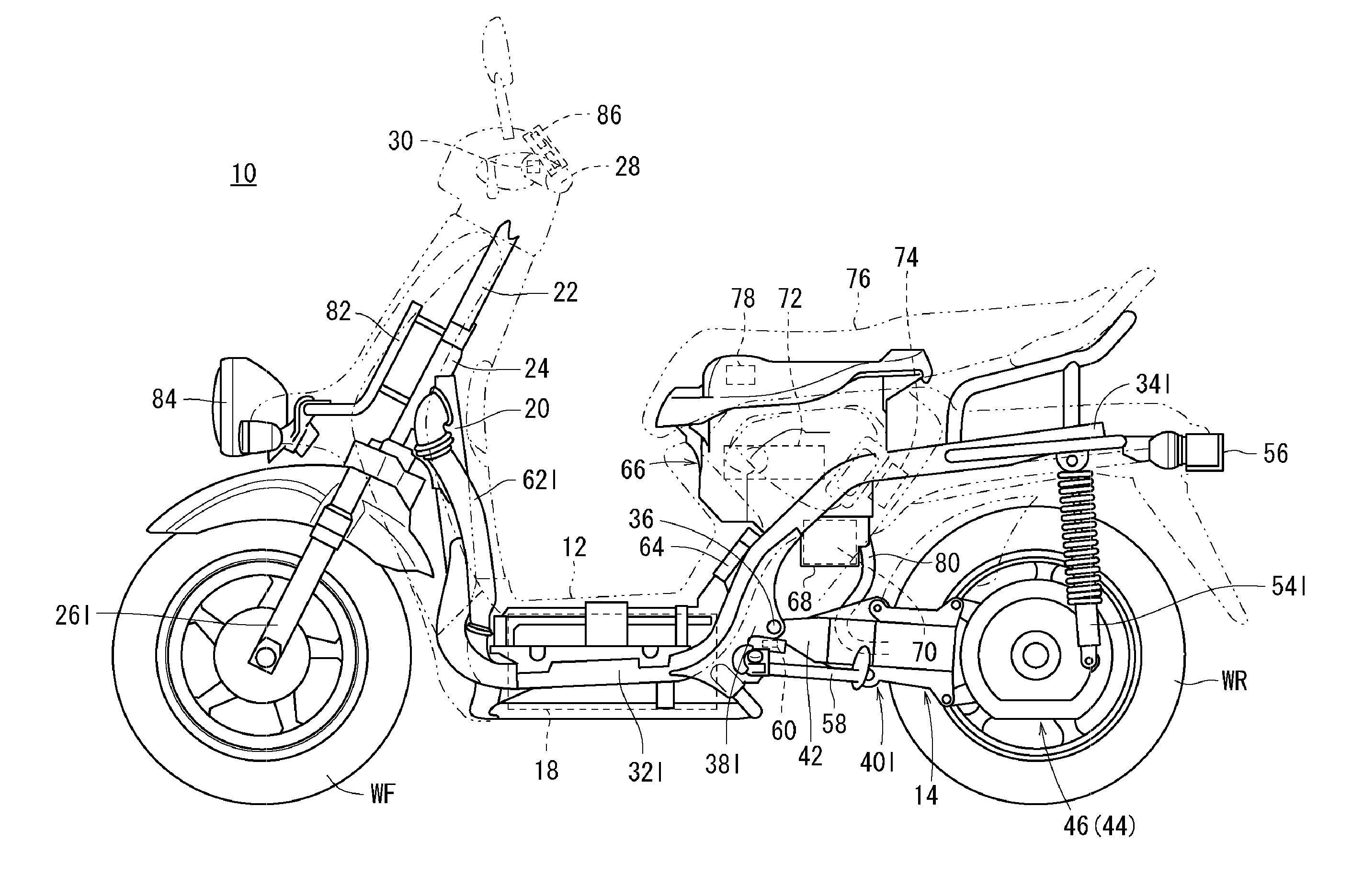
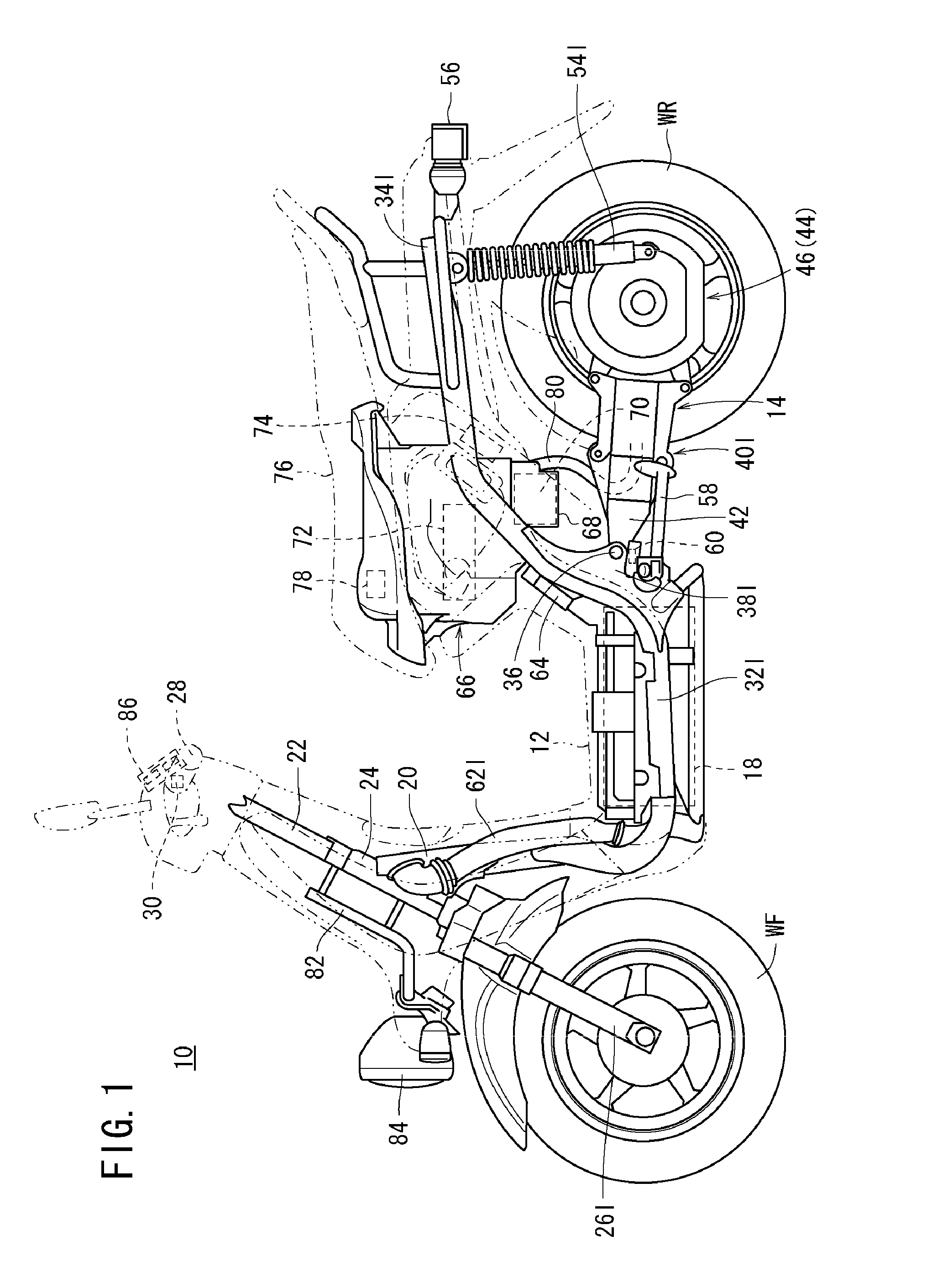
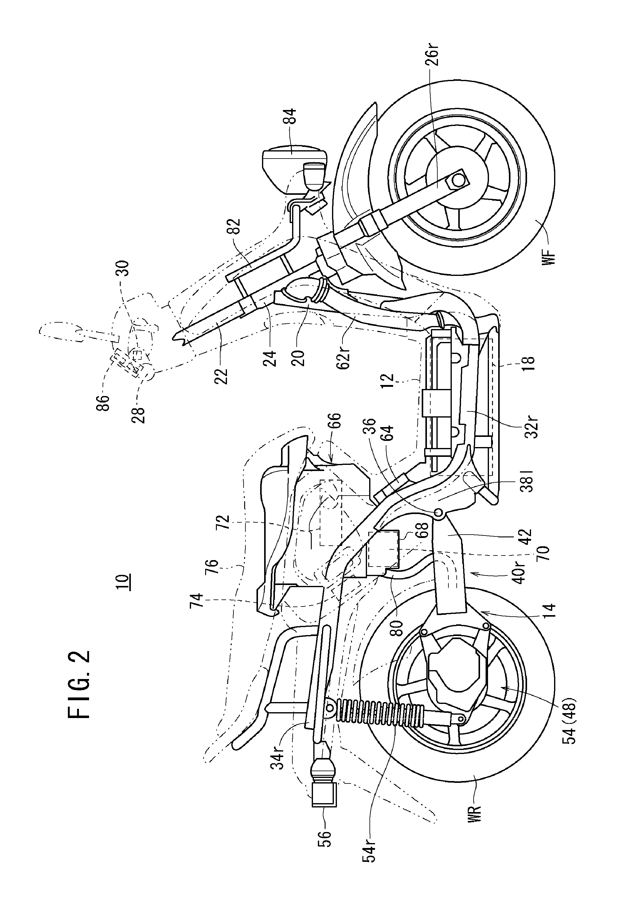
[0067]FIG. 1 is a left side view of a two-wheeled electric vehicle (electric vehicle) 10 according to this embodiment. FIG. 2 is a right side view of the two-wheeled electric vehicle 10.

[0068]The two-wheeled electric vehicle 10 is a scooter type two-wheeled vehicle having a step floor 12, in which a rear wheel WR is driven by rotational drive force of a motor 16 (see FIG. 3) provided in a swing arm 14. A high-voltage (for example, 72 V) main battery 18 for supplying electric power to the motor 16 has plural modules with plural battery cells connected in series.

[0069]A head pipe 24 rotatably journaling a steering stem 22 is coupled to an upper end of a main frame 20. A pair of left and right front forks 26l and 26r rotatably journaling a front wheel WF is mounted to the steering stem 22. The front wheel WF can be s...


PUM


Abstract

An electric vehicle includes a double-sided swing arm that supports a motor shaft, an axle, and a wheel by supporting a motor on one side of the wheel and a reduction mechanism on the other side of the wheel. In this case, the swing arm is composed of, on the one side of the wheel, plural separable arm portions. The arm portions have respective separation points on an outside or outer periphery of the wheel. With the components arranged in this manner, weight balance of the electric vehicle is easily achieved, and the operational efficiency of mounting, removal, and replacement of the wheel and the motor is improved.

Description

CROSS-REFERENCE TO RELATED APPLICATION[0001]The present application claims priority under 35 U.S.C. §119 to Japanese Patent Application No. 2011-081259, filed Mar. 31, 2011. The entire contents of the above-identified application are hereby incorporated by reference.BACKGROUND OF THE INVENTION[0002]1. Field of the Invention[0003]The present invention relates to an electric vehicle in which an output of a motor is transmitted to an axle through a reduction mechanism, thereby rotating a wheel.[0004]2. Description of Background Art[0005]In the past, various electric vehicles have been proposed in which an output of a motor is transmitted to an axle through a reduction mechanism, thereby rotating a wheel.[0006]For example, in JP-A No. 2008-100609, there is proposed an electric vehicle in which, on one side of a wheel, a motor and a reduction mechanism are built into a swing arm, and a brake is provided within the wheel, while on the other side of the wheel, an axle passing through the w...

Claims


Application Information

Patent Timeline
Patent Type & Authority Applications(United States)
IPC IPC(8): B62M7/12B62K11/10
CPCB62M7/12B62K2204/00B62M6/65B60K7/00B62K11/10B62K25/26
Inventor KAWAGUCHI, ATSUSHIKOBAYASHI, YOSHITAKANAKASHIMA, MASAHIROTOMINAGA, TAKASHI
Owner HONDA MOTOR CO LTD
Why Eureka
Try Eureka