Vehicle underbody structure

a technology for underbody structures and vehicles, which is applied in the direction of machines/engines, jet propulsion mountings, transportation items, etc., can solve the problems of increasing the point at which vibrations are inputted to the vehicle body, and the noise vibration characteristics of the vehicle body become worse, so as to improve the noise vibration characteristics of the vehicle body and increase the weight of the vehicle body

Inactive Publication Date: 2005-08-04
TOYOTA JIDOSHA KK
View PDF15 Cites 14 Cited by
  • Summary
  • Abstract
  • Description
  • Claims
  • Application Information

AI Technical Summary

Benefits of technology

[0007] In consideration of these facts, the present invention provides a vehicle underbody structure that can improve t

Problems solved by technology

However, when the fuel tank and the exhaust muffler are attached to frame members of the vehicle body, the points at which vibrations are inputted to the vehicle body increase when the fuel tank and the exhaust muf

Method used


Image

  • Vehicle underbody structure
  • Vehicle underbody structure
  • Vehicle underbody structure

Examples


Embodiment Construction

[0024] An embodiment of a vehicle underbody structure of the invention will be described in accordance with FIGS. 1 to 4.

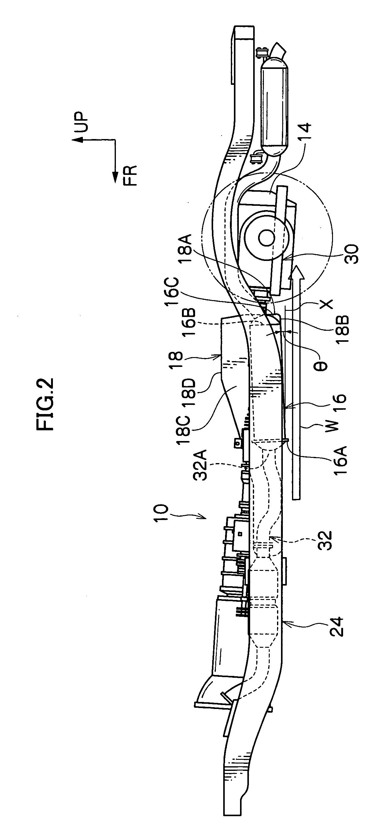
[0025] In the drawings, arrow FR represents a vehicle body front direction, arrow UP represents a vehicle body up direction, and arrow IN represents a vehicle width-direction inner side, i.e., a direction toward a vehicle inner side along a vehicle width direction.

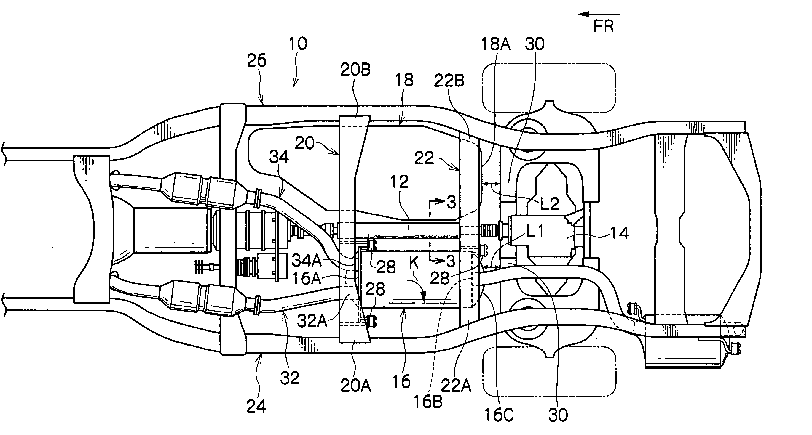
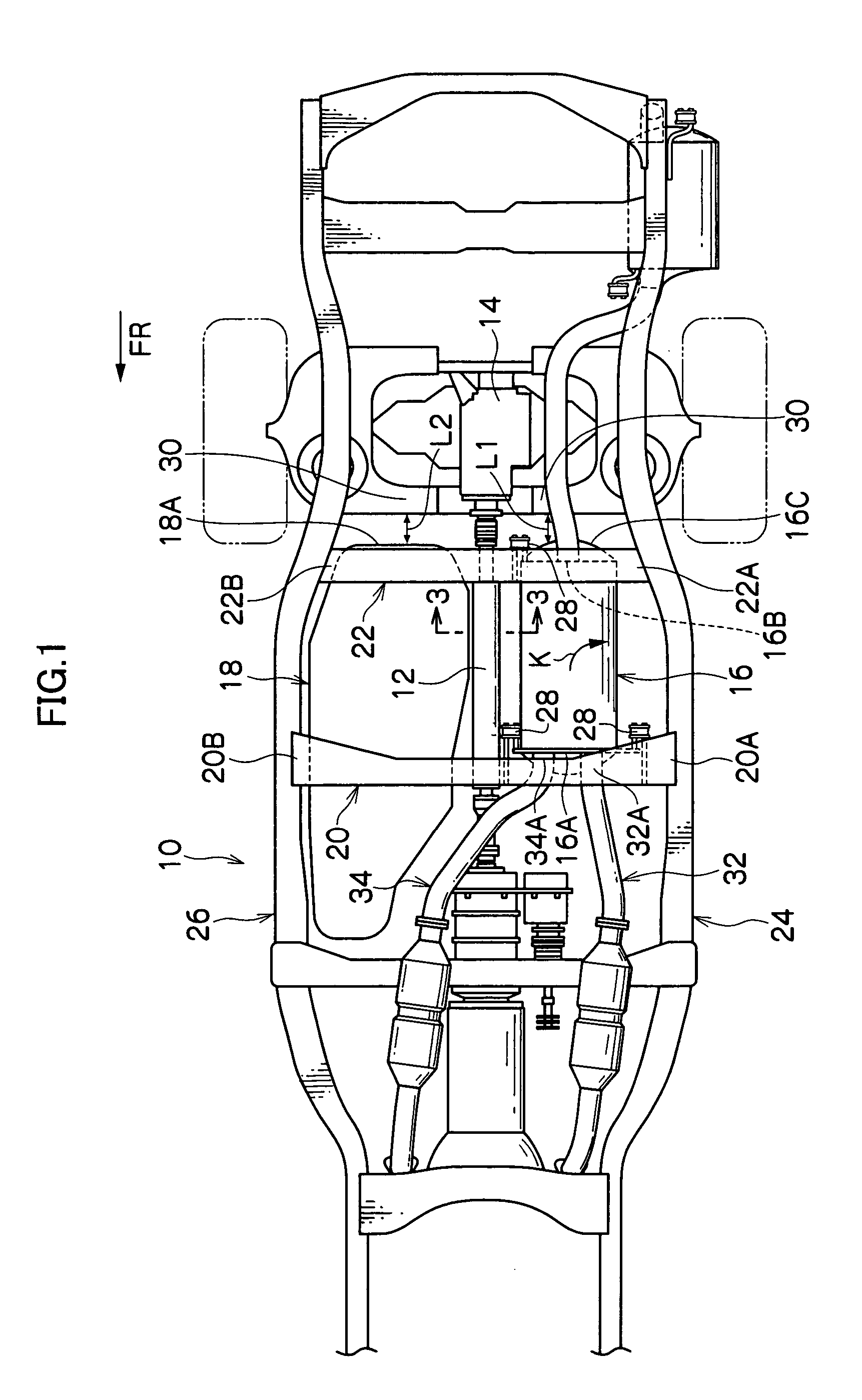
[0026] As shown in FIG. 1, a vehicle body 10 of an automobile in the present embodiment is a vehicle body disposed with a frame, such as an SUV (Sports Utility Vehicle) or a pickup truck. A drive shaft 12 is disposed along a vehicle body longitudinal direction in a vehicle width-direction center portion of the vehicle underbody. A differential 14 is coupled to a rear end portion of the drive shaft 12.

[0027] An exhaust muffler 16 configuring part of an exhaust pipe is disposed in the vehicle body longitudinal direction parallel to the drive shaft 12 at the left side of the drive shaft 12 at a longitudi...


PUM


Abstract

At the underside of a vehicle body, a fuel tank and an exhaust muffler are disposed alongside of each other along a vehicle body longitudinal direction, with a drive shaft being disposed between the fuel tank and the exhaust muffler. The front and rear of the fuel tank are attached with tank bands to two cross members. The exhaust muffler is attached to the two cross members via rubber supports. Because the exhaust muffler and the fuel tank are attached to common cross members, the noise vibration characteristics of the vehicle body are improved while suppressing an increase in the weight of the vehicle body.

Description

CROSS-REFERENCE TO RELATED APPLICATION [0001] This application claims priority under 35 USC 119 from Japanese Patent Application No. 2004-25940, the disclosure of which is incorporated by reference herein. BACKGROUND OF THE INVENTION [0002] 1. Field of the Invention [0003] The present invention relates to a vehicle underbody structure, and in particular to a vehicle underbody structure of an automobile. [0004] 2. Description of the Related Art [0005] Conventionally, with respect to a vehicle underbody structure of an automobile, a configuration has been known where a fuel tank is disposed at one side of a rear propeller shaft and at the side where the front propeller shaft is positioned, and where an exhaust muffler (also called a “silencer”) is disposed at the other side of the rear propeller shaft. [0006] However, when the fuel tank and the exhaust muffler are attached to frame members of the vehicle body, the points at which vibrations are inputted to the vehicle body increase wh...

Claims


Application Information

Patent Timeline
IPC IPC(8): B60K13/04B60K15/063B62D21/02B62D25/20
CPCB60K13/04B62D25/20B62D21/02B60K15/063
Inventor MABUCHI, TOMOKIMINEDA, KOJIISHIKAWA, TAKASHI
Owner TOYOTA JIDOSHA KK
Why Eureka
Try Eureka