Bumper reinforcement

a bumper reinforcement and bumper technology, applied in bumpers, vehicle components, propulsion parts, etc., can solve the problems of local breakage of bumper reinforcement and penetration into the cabin side, and achieve the effect of suppressing engine disconnection, and effectively absorbing collision energy

Active Publication Date: 2019-03-21
TOYOTA JIDOSHA KK +1
View PDF0 Cites 14 Cited by
  • Summary
  • Abstract
  • Description
  • Claims
  • Application Information

AI Technical Summary

Benefits of technology

[0022]The bumper reinforcement of the second aspect may suppress the engine or the transaxle from interfering with vehicle frame members due to the engine and the transaxle, which are in a connected state, being disconnected.
[0023]The bumper reinforcement of the third aspect may effectively transmit the collision load in the vehicle longitudinal direction via the side members.
[0024]The bumper reinforcement relating to the fourth aspect may suppress local breakage of the bumper reinforcement at the ve

Problems solved by technology

However, in a case of colliding with a collision body that is relatively small such as a pole or the like, due to collision load being applied locall

Method used


Image

  • Bumper reinforcement
  • Bumper reinforcement
  • Bumper reinforcement

Examples


first exemplary embodiment

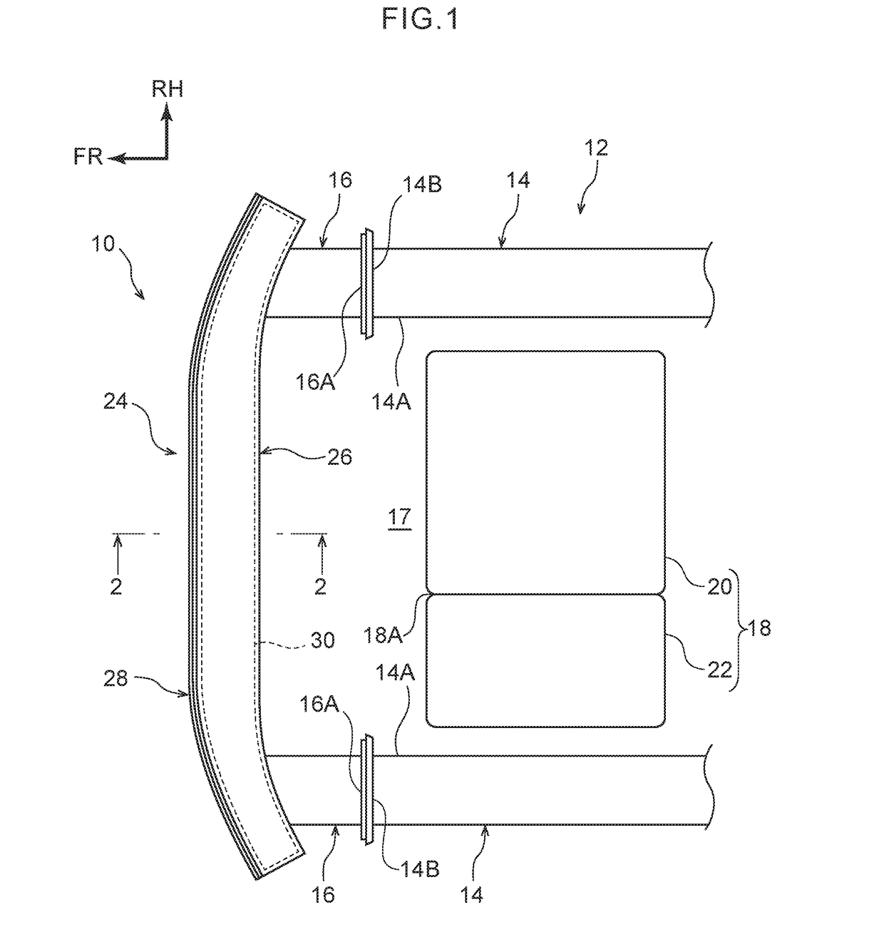
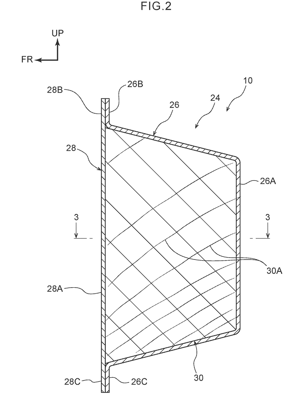
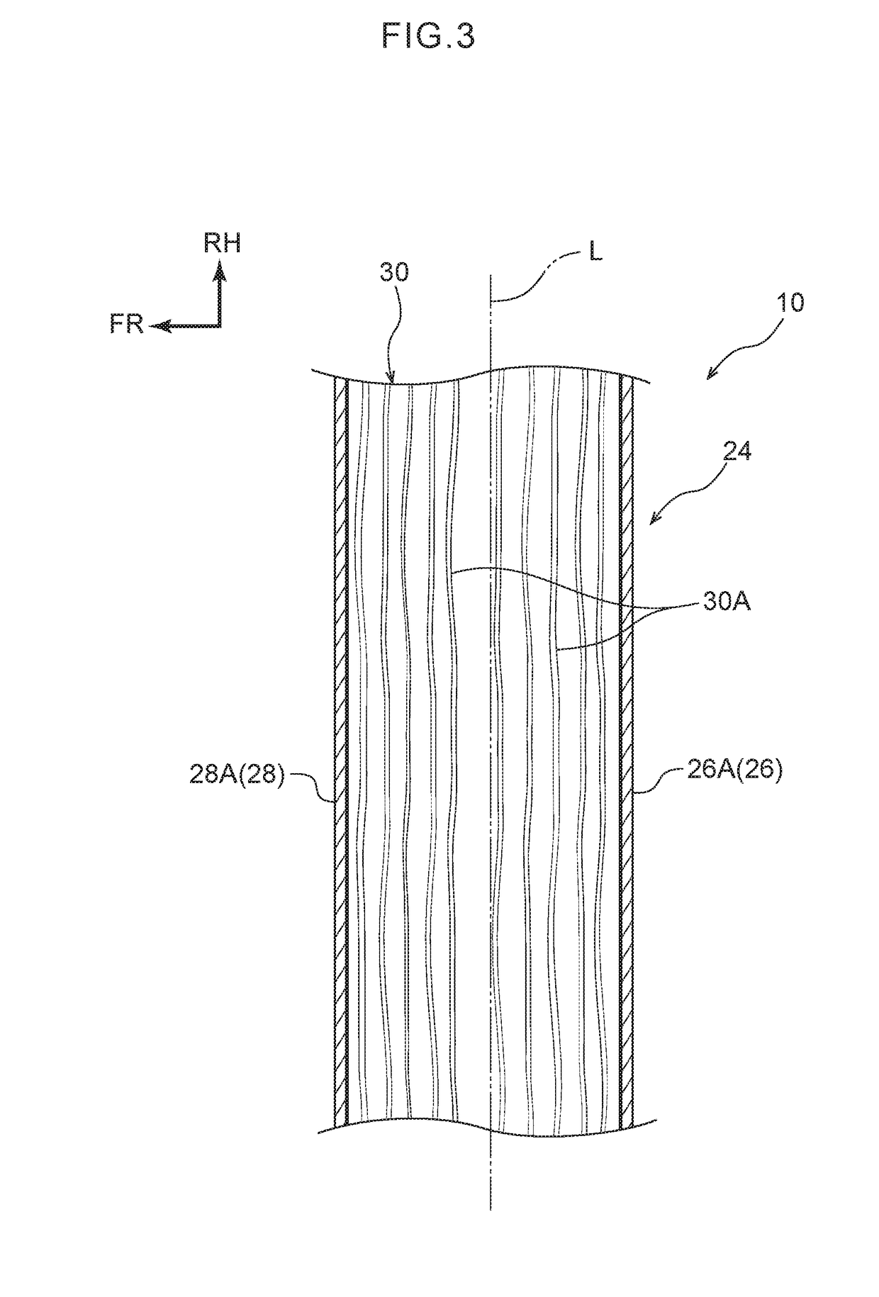
[0041]A bumper reinforcement 10 relating to a first exemplary embodiment is described with reference to the drawings. Note that arrow FR, arrow UP and arrow RH that are marked appropriately in the respective drawings indicate the forward direction of the vehicle, the upward direction, and the vehicle right side, respectively. Hereinafter, when explanation is given by merely using longitudinal, vertical and left-right directions, they refer to the longitudinal of the vehicle longitudinal direction, the vertical of the vehicle vertical direction, and the left and the right in the vehicle transverse direction when facing in the advancing direction, unless otherwise indicated.

[0042]As shown in FIG. 1, the bumper reinforcement 10 relating to the present exemplary embodiment is applied to the vehicle front portion of a vehicle 12. A pair of left and right front side members 14 that extend in the vehicle longitudinal direction are provided at the vehicle front portion of the vehicle 12.

[00...

first modified example

[0061]As shown in FIG. 5A, a bumper reinforcement 40 relating to a first modified example has a bumper main body portion 42 that is formed by extrusion molding of a metal. The bumper main body portion 42 is structured to include vertical walls 42A that are disposed with an interval therebetween the vehicle longitudinal direction, and lateral walls 42B that connect the upper end portions and the lower end portions of the vertical walls 42A together in the vehicle longitudinal direction. Further, the vehicle vertical direction central portions of the vertical walls 42A are connected in the vehicle longitudinal direction by a partitioning wall 42C. Therefore, the bumper main body portion 42 is a structure having two closed cross-sections in the vertical direction. An upper side reinforcing member 43 that is formed of wood and is block-shaped is disposed within the closed cross-section that is at the upper side, and a lower side reinforcing member 44 that is formed of wood and is block-...

second modified example

[0063]As shown in FIG. 5B, a bumper reinforcement 46 relating to a second modified example has a bumper main body portion 48 that is formed by extrusion molding of a metal. The bumper main body portion 48 is structured to include vertical walls 48A that are disposed with an interval therebetween the vehicle longitudinal direction, and lateral walls 48B that connect the upper end portions and the lower end portions of the vertical walls 48A together in the vehicle longitudinal direction. Further, an upper partitioning wall 48C and a lower partitioning wall 48D that connect the vertical walls 48A in the vehicle longitudinal direction are provided between the upper and lower lateral walls 48B. The closed cross-section at the interior of the bumper main body portion 48 is divided into three equal portions in the vertical direction by the upper partitioning wall 48C and the lower partitioning wall 48D. An upper side reinforcing member 45 that is formed of wood and is block-shaped is disp...


PUM


Abstract

The present disclosure provides a bumper reinforcement including: a bumper main body portion extending in a vehicle transverse direction and is provided at a vehicle longitudinal direction outer side of a pair of left and right side members, the pair of left and right side members being disposed at a vehicle front portion or a vehicle rear portion and extending in a vehicle longitudinal direction; and a reinforcing member formed of wood and is block-shaped, and that is disposed within a cross-section of at least a vehicle transverse direction central portion of the bumper main body portion, an axially central direction of annual growth rings of the wood of the reinforcing member being set to a direction that runs along the vehicle transverse direction.

Description

CROSS-REFERENCE TO RELATED APPLICATION[0001]This application is based on and claims priority under 35 USC 119 from Japanese Patent Application No. 2017-177503 filed on Sep. 15, 2017, the disclosure of which is incorporated by reference herein.BACKGROUNDTechnical Field[0002]The present disclosure relates to a bumper reinforcement.Related Art[0003]Japanese Patent Application Laid-Open (JP-A) No. 2017-13722 discloses a structure in which plural partitioning members, which are plate-shaped and are made of steel, are provided within the cross-section of a bumper reinforcement. Further, JP-A No. 2014-184899 discloses a structure in which impact absorbing members that are made of wood are provided at portions of crash boxes that are between a bumper reinforcement and side members. In this JP-A No. 2014-184899, the impact absorbing members are crushed easily in the axial direction by making the axially central directions of the annual growth rings of the impact absorbing members coincide wi...

Claims


Application Information

Patent Timeline
IPC IPC(8): B60R19/22B60R19/03
CPCB60R19/22B60R19/03B60K5/04B60R2019/1813B60R19/02B60R19/34B60R19/18B60R2019/1806
Inventor TAKAYANAGI, JUNICHIMIURA, TOSHIHISA
Owner TOYOTA JIDOSHA KK
Why Eureka
Try Eureka