Packaging machine

Inactive Publication Date: 2006-10-12
ISHIDA CO LTD
View PDF9 Cites 12 Cited by
  • Summary
  • Abstract
  • Description
  • Claims
  • Application Information

AI Technical Summary

Benefits of technology

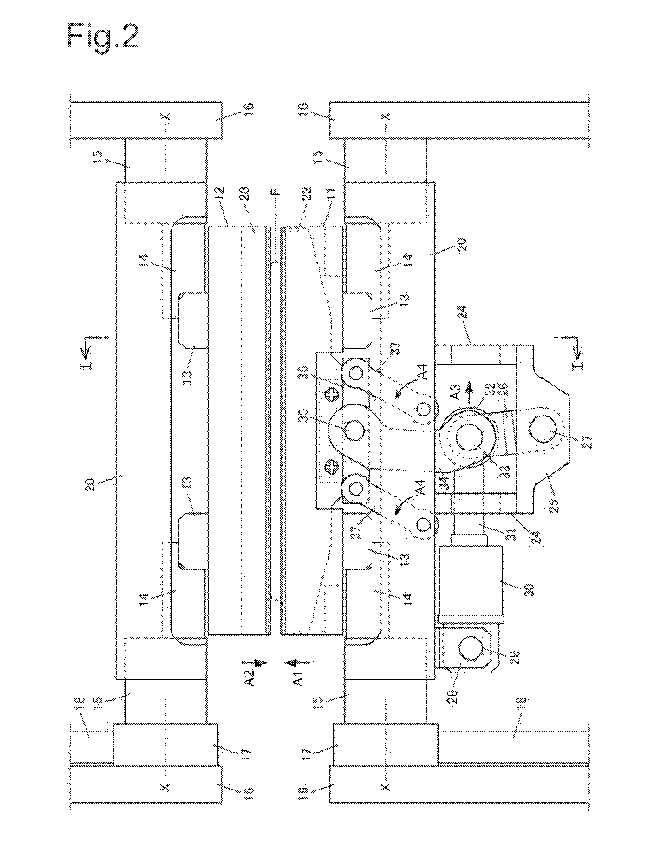
[0021] Next, according to the fifth aspect, since the mobile member that moves freely between an inhibiting position that inhibits the pressing member from retracting and a permitting position that permits the pressing member to retract is used as the stopping unit, the large amount of pressure necessary for cutting can be reliably secured by this mobile member.
[0022] Next, according to the sixth aspect, since the pressing force of the pressing member is adjusted, the cutting pressure can be altered in various degrees according to, for example, the type and the thickness of the packing material, the cutting time, and any other factor

Problems solved by technology

However, with melting-type cutting devices such as those described above, since the film is melted with heat and cut through with pressure, the pressing member must be pressed into the receiving member with a relatively large amount of force.
However, the result of this is that a conventional melting-type cutting device has drawbacks in that it is constantly cutting bags and cannot switch back and forth from a cutting to a non-cutting mode.
However, with the cutter device disclosed in Japanese Examined Utility Model Application No. 61-43687, when either a cutting blade or a perforating blade is used, there is no support for bearing the large amount of force applied from the front of the blade, and therefore the blade retracts, and the film cannot be cut through with the large amount of force applied.
In addition, in the packaging machine disclosed in Japanese Patent No. 2849071, when perforating needles configured to be capable of

Method used


Image

  • Packaging machine
  • Packaging machine
  • Packaging machine

Examples


first embodiment

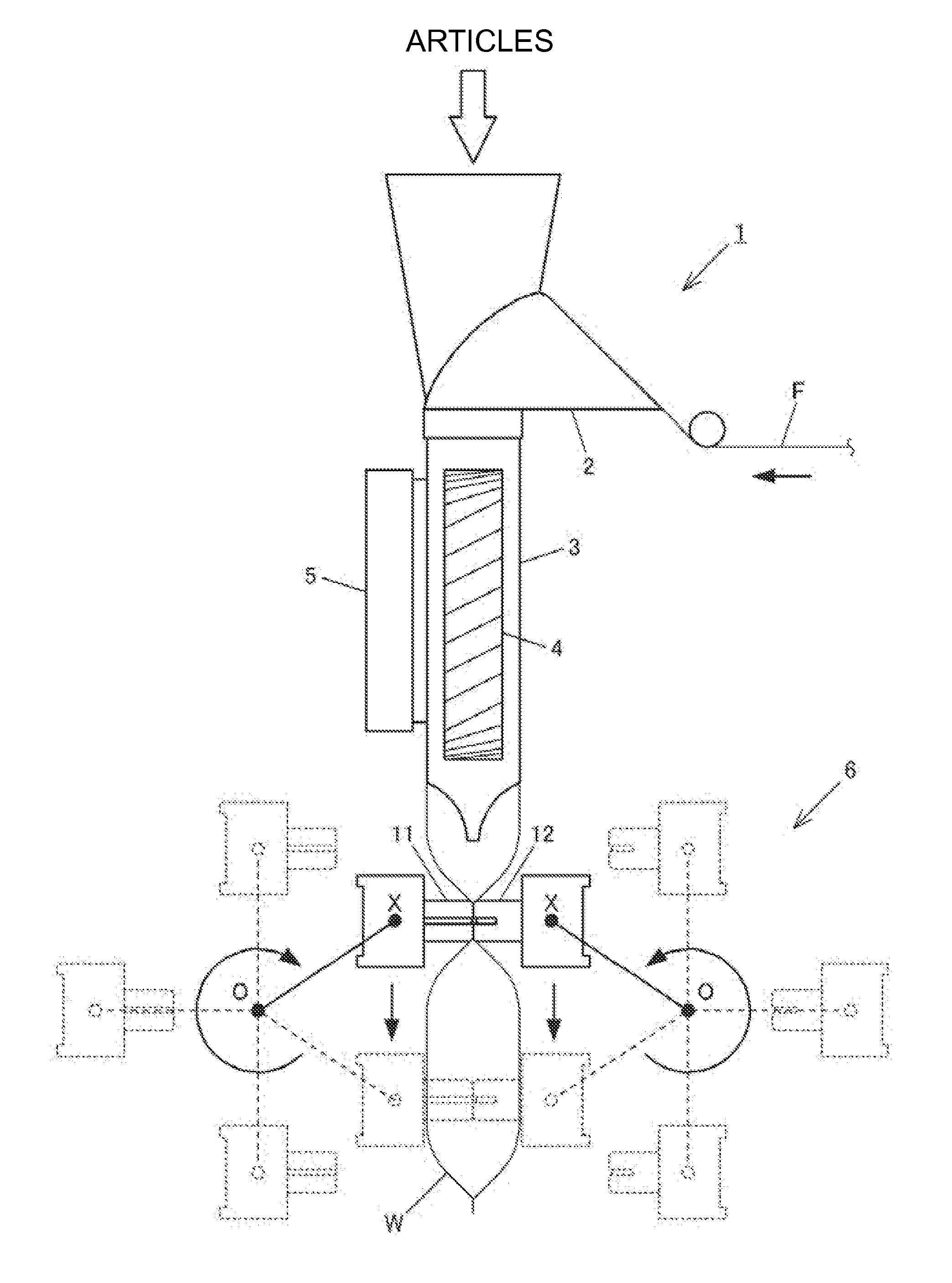
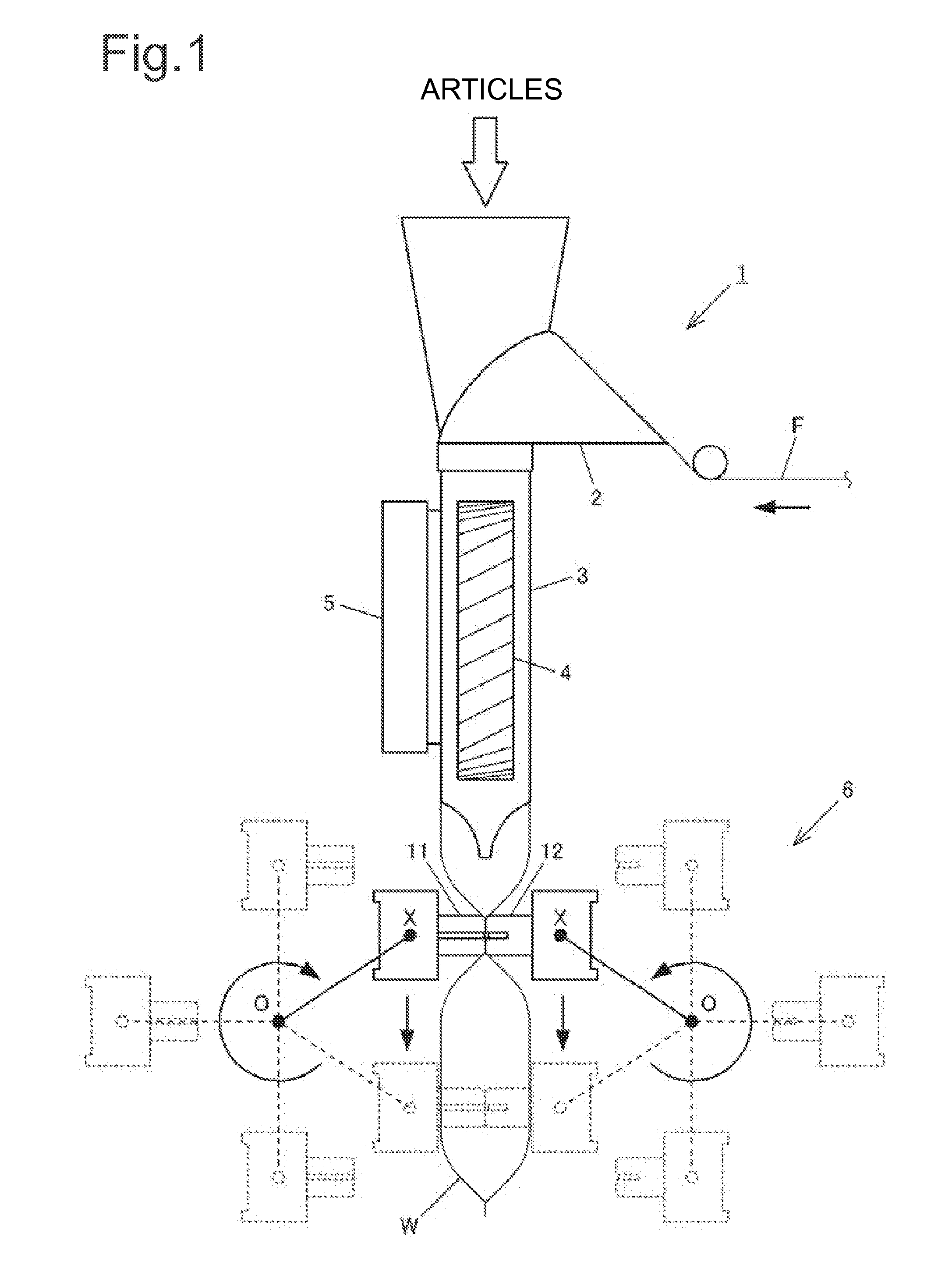
[0035] In this embodiment, the present invention is applied to a packaging machine 1 shown in FIG. 1. Specifically, this packaging machine 1 is a conventional lengthwise pillow-type bag making machine, comprising a former 2, a tube 3, pull-down belts 4, 4 (only one is shown), a lengthwise sealing device 5, and a widthwise sealing device 6. A heat-melting film F made of a synthetic resin or the like is conveyed as shown by the arrow, and rolled into a cylinder by the former 2. The cylindrical film F is suspended down along the periphery of the tube 3, and as the film is conveyed further downward by the pull-down belts 4, 4, the overlapping lateral edges of the film are sealed along the length thereof by being heated and welded by the lengthwise sealing device 5, and the film is further sealed along the width thereof by being heated and welded by the widthwise sealing device 6. While the bag W is thereby being manufactured, articles are filled into the bag W from above via the tube 3....

second embodiment

[0052] A second embodiment of the present invention will be described with reference to FIGS. 6 and 7. The same reference numbers are used for structural elements identical to or resembling those of the first embodiment, and only the characteristics unique to this embodiment are described below. In the first embodiment, a toggling mechanism was used as the force augmenting mechanism for transmitting the motive energy of the air cylinder 30 to the pressing member 22; however, in the second embodiment, a cam mechanism is used as the force augmenting mechanism.

[0053] In the second embodiment, a widthwise sealing device 6 has sealing jaw units. Two of these jaw units come in contact and sandwich the film F, where the pressing members 22 are provided on the first jaws 11 and the receiving members 23 are provided on the second jaws 12. However, only a jaw unit of the first jaws 11 is described below as an example, shown in FIG. 6.

[0054] Specifically, this jaw unit includes two bearings ...

third embodiment

[0067] A third embodiment of the present invention will be described with reference to FIG. 8. The same reference numbers will be used to denote structural elements identical or similar to those in the first and second embodiments, and only the characteristics unique to the third embodiment will be described. In the first and second embodiments, the toggling mechanism or the cam mechanism were used as the force augmenting mechanism, as the stopping unit for stopping the pressing members 22 from behind when the pressing members 22 were in contact under pressure, i.e., when the bags W were being cut; however, in the third embodiment, a mobile member is used.

[0068] As shown in FIG. 8, the sealing jaw unit has a unit case 81 through which runs a shaft, shown by the two-dot chain line, that serves as a rotational axis X. An air cylinder 84 is housed in this case 81, and a bracket 86 is connected to the rod end 85 thereof. The bracket 86 extends past the opening 83 formed in a dividing p...


PUM

PropertyMeasurementUnit
Forceaaaaaaaaaa
Pressureaaaaaaaaaa
Angleaaaaaaaaaa

Abstract

A packaging machine includes a cutting device having a configuration wherein a pressing member provided in one jaw of a pair of sealing jaws that come into contact with each other on both sides of a cylindrical film comes into contact under pressure with a receiving member provided in the other jaw, whereby the cylindrical film being sealed by the sealing jaws is melted. The packaging machine also includes a cylinder for switching the pressing member in contact position under pressure with the receiving member or in non-contact position when the sealing jaws are in mutual contact, and a toggling mechanism configured with a cylinder rod and links. When the pressing member is brought into the contact position under pressure, the links of the toggling mechanism secure the pressing member from behind.

Description

BACKGROUND OF THE INVENTION [0001] 1. Field of the Invention [0002] The present invention relates to a packaging machine, and more particularly to packaging machines that have a cutting device installed on a sealing device. [0003] 2. Background Information [0004] In conventional practice, packaging machines generally form bags, into which articles are placed, by sealing a heat-melting film rolled into a cylinder lengthwise and widthwise, where the heat-melting film is made of a material such as a synthetic resin. Such packaging machines are commonly equipped with a cutting device for cutting the widthwise sealed areas along the width to separate the individual bags. Known examples of such cutting devices include melting-type cutting devices as disclosed in Japanese Examined Utility Model Application No. 6-34264 (FIG. 1), wherein the film is held between a pressing member, described as a “cutter blade” in this reference, and a receiving member, described as a “cutter receiving blade”...

Claims


Application Information

Patent Timeline
IPC IPC(8): B31C11/02B65B51/10
CPCB65B61/08B65B51/306B29C65/18B29C65/305B29C65/7451B29C66/1122B29C66/232B29C66/4312B29C66/81419B29C66/81431B29C66/81435B29C66/8161B29C66/8221B29C66/8242B29C66/83513B29C66/83543B29C66/849B29C66/92443B29C66/92921
Inventor HASHIMOTO, SATOSHIKONDO, MASASHIICHIKAWA, MAKOTO
Owner ISHIDA CO LTD
Why Eureka
Try Eureka