Electrical connector

a technology of electrical connectors and connectors, applied in the direction of charging stations, transportation and packaging, coupling device connections, etc., can solve the problems of tearing off the electrical connecting cable, damage to the plug-type connection or the cable, and the plug-type connection is not configured

Inactive Publication Date: 2013-09-17
SCHALTBAU GMBH
View PDF26 Cites 30 Cited by
  • Summary
  • Abstract
  • Description
  • Claims
  • Application Information

AI Technical Summary

Benefits of technology

[0007]The present invention is, therefore, based on the object to develop the plug-type connection of the aforementioned kind further in such a way that the plug is optimally secured against slipping out of the socket up to a certain tensile load, even if the cable is tensioned obliquely. At the same time, damages to the socket, plug and especially the cable are effectively prevented.
[0009]The flexibility of the plug virtually allows the plug to bend. Thus, the rear end of the plug, from which the cable is passed out, can be pivoted relative to the front part of the plug, which is plugged into the socket. The kink formed in the cable at the point where the cable enters into the rear end of the plug is, therefore, extremely small, even if the cable is tensioned very obliquely, so that damage to the cable at this point is avoided. Due to the two pivot axes provided in accordance with the invention, the retaining element, which secures the plug against slipping out of the socket, can be repositioned in an optimum manner if the plug is deformed as a result of an obliquely tensioned cable. Thus, the retaining element is always ideally aligned so as to secure the rear plug part up to a certain tensile load. The retaining element pivots so to speak along with the rear part of the plug.
[0012]In a preferred embodiment of the present invention the second pivot axis stands perpendicularly on a plane in which the first pivot axis lies. By this, the retaining element always releases the plug reliably as of a certain tensile load, even if the cable is tensioned obliquely. Further, it is an advantage if the second pivot axis coincides with an imagined axis about which the second plug part can be displaced relative to the first plug part from the straight position to the oblique position due to the flexibility of the plug, if the plug is plugged in. Preferably, the first pivot axis thereby always lies in a plane that runs orthogonally relative to the second plug axis. By this, too, it is ensured that the retaining element always releases the plug reliably, even if the cable is tensioned obliquely. Also, the second pivot axis may nearly coincide with the imagined axis.
[0016]In another, specifically preferred embodiment of the present invention two clamps are provided as retaining elements, which extend substantially parallel to each other and are each rotatable with one of their ends about the mutual first pivot axis, wherein the two clamps are arranged symmetrically relative to the second plug axis. The two clamps can thus encompass the rear plug end, where the cable comes out, on both sides of the cable, thereby reliably securing the plug against slipping out of the plug-in opening. The symmetrical arrangement of the two clamps allows a uniform load handling and prevents the plug from tilting relative to the retaining elements. The two clamps may be connected to each other rigidly, so that they open simultaneously as soon as a certain pull-out force acting on the plug is reached. Alternatively, the two clamps may also be movable independently of each other.
[0017]It is specifically preferred that each clamp comprises at least one form closure element, which is engaged with a corresponding form closure element of the plug as soon as the clamps secure the plugged in plug against slipping out of the plug-in opening. This guarantees a stable support of the plug in the socket until the predetermined maximum load is reached. For example, a recess may be formed in the clamp, which interacts with a bump formed at the end of the plug or a corresponding protrusion at the end of the plug.
[0019]Furthermore, in another preferred embodiment of the present invention, a return spring associated with the second pivot axis is provided, by means of which the retaining element is preloaded about the second pivot axis into a preferred position in which the retaining element is oriented to optimally secure the plugged in plug if the second plug part is in the straight position. Preferably, the first pivot axis in the preferred position lies in a plane that extends perpendicularly to the longitudinal axis of the plug. This embodiment ensures that the plug is straightened, if feasible, if the load is small.

Problems solved by technology

The problem of plug-type connections of this kind is that a strong tensile load acting on the plug or the cable connected to the plug may cause damage to the plug-type connection or the cable.
The plug-type connection is not configured, however, to couple a towing vehicle and a trailer to each other mechanically.
This negligence may result in the movement of the towing vehicle without the trailer which, as a rule, causes damage to the plug-type connection and results in the tearing off of the electrical connecting cable.
A problem occurs if the tensile load acting on the plug and the cable does not act in the longitudinal direction of the plug.
With respect to cables tensioned obliquely relative to the longitudinal direction of the plug this solution is suitable only to a limited extent, however.
Furthermore, the resultant cable run has proved to be disadvantageous.
If the pull-out angles are very oblique, a strong kink in the cable is caused at this point.

Method used


Image

  • Electrical connector
  • Electrical connector
  • Electrical connector

Examples


Embodiment Construction

[0027]In the following description, like components will be designated with like reference numbers. If a drawing contains reference numbers that are not explained in more detail in the associated description of the drawings, reference will be made to preceding figure descriptions or figure descriptions to follow.

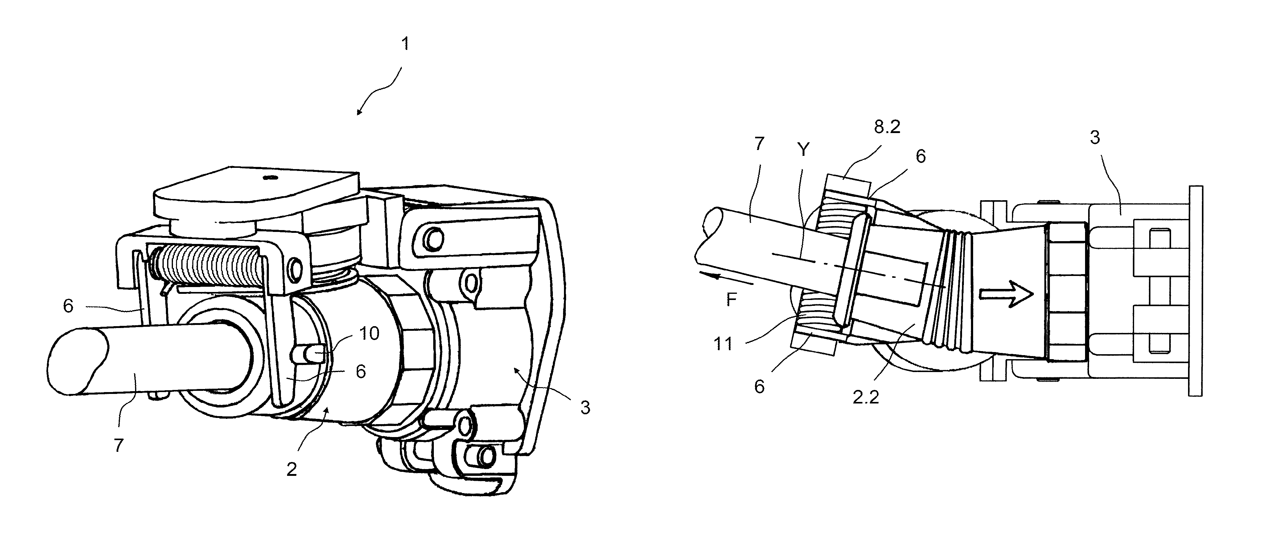
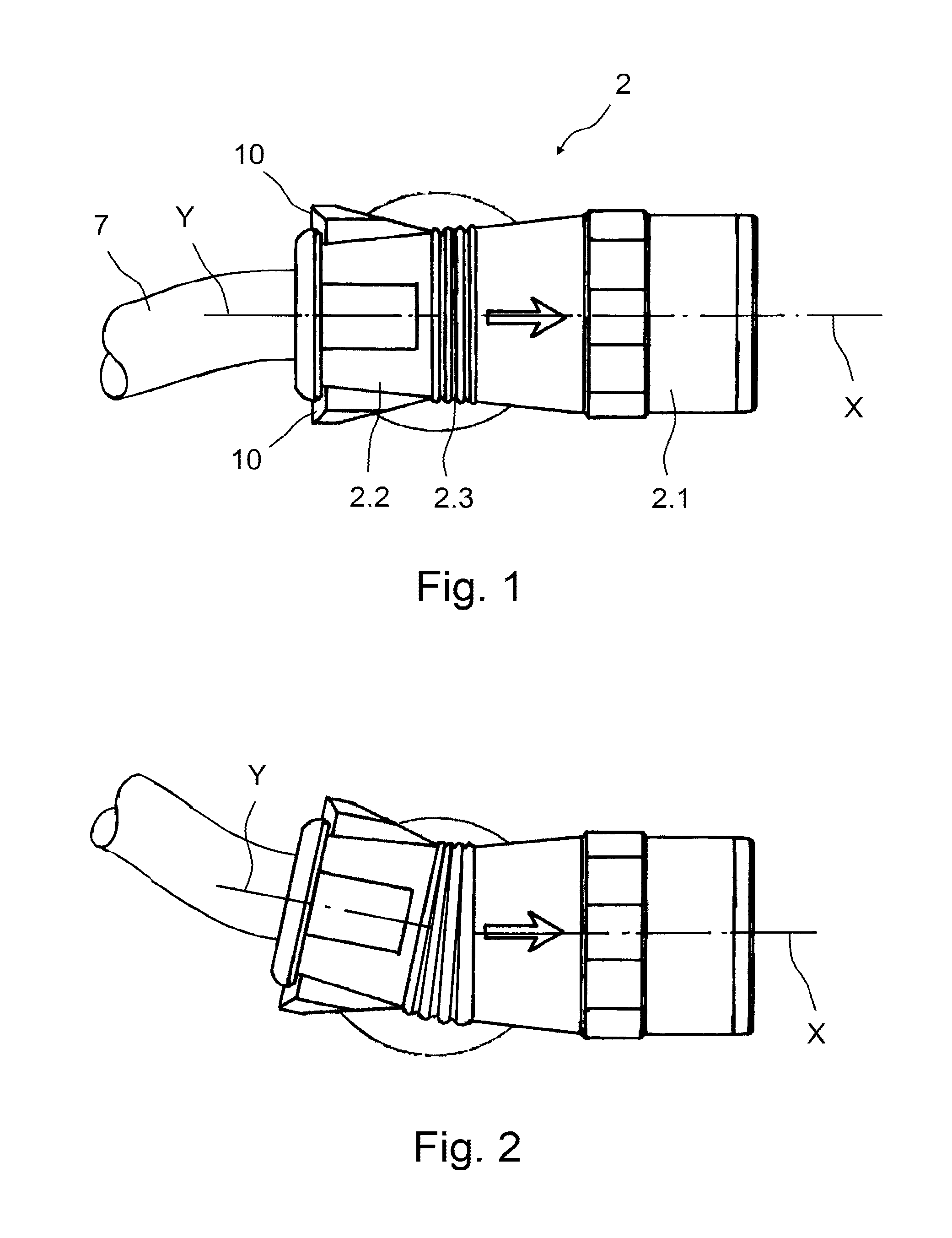
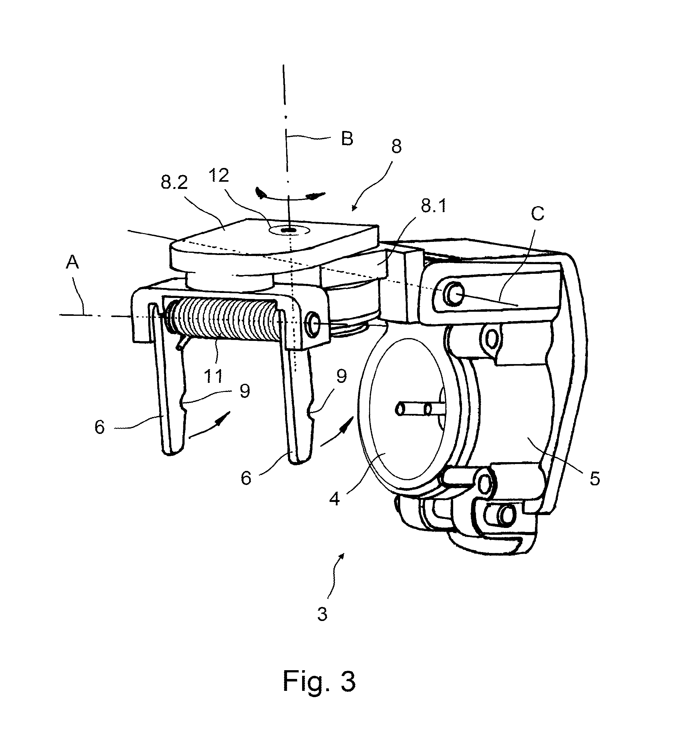
[0028]FIG. 1 shows the plug 2 of a plug-type connection according to the invention. It comprises a first front plug part 2.1 and a second rear plug part 2.2, the two plug parts 2.1 and 2.2 being connected to each other by a flexible plug part 2.3. The plug 2 can be plugged into the socket illustrated in FIG. 3 with the first front plug part 2.1. The cable 7 is passed out of the second rear plug part 2.2. Furthermore, two protrusions 10 can be seen on the rear plug part 2.2, whose function will be explained below. FIG. 1 shows the plug in an unloaded condition. The longitudinal axis X of the first plug part 2.1 coincides in this condition of the plug with the longitudinal axi...


PUM


Abstract

Disclosed is a plug-type connection having a plug and a socket with a plug-in opening for the plug. The socket includes a socket housing and at least one retaining element connected to the socket housing and movable about a first pivot axis. The retaining element secures the plug plugged into the plug-in opening against slipping out of the plug-in opening. A means is provided to displace the retaining element about the first pivot axis out of the position securing the plug against slipping out, thereby releasing the plug, if a specific force acting on the plug opposite to the plug-in direction is exceeded.

Description

CROSS-REFERENCE TO RELATED APPLICATIONS[0001]This application claims priority to German Patent Application No. 10 2012 007 911.7, filed Apr. 20, 2012, the disclosure of which is incorporated by reference herein.BACKGROUND OF THE INVENTION[0002]Plug-type connections are known in the prior art, whose socket is closed by a lid if the plug is not plugged in, the lid being rotatably mounted on the socket housing. In most cases, the lid is preloaded by means of a spring, so as to close the plug-in opening of the socket automatically as soon as the plug is pulled out of the socket. Most of the plug-type connections of this kind known in the prior art have a snap-in nose formed on the lid of the socket which, if the plug is plugged in, is engaged with or engaged behind the plug itself or a suitable protrusion formed on the plug, so that the plug is secured against slipping out of the socket. The spring preload of the lid makes sure that the snap-in nose of the socket lid remains constantly ...

Claims


Application Information

Patent Timeline
Patent Type & Authority Patents(United States)
IPC IPC(8): H01R13/44
CPCB60D1/64H01R13/502H01R13/6315B60L11/1818H01R13/6395Y02T90/14B60L2270/32B60L2270/34Y02T10/7005H01R2201/26B60L53/16Y02T10/70Y02T10/7072
Inventor MUELLER, BENNO
Owner SCHALTBAU GMBH
Why Eureka
Try Eureka