Magnet rotor and electromagnetically-driving device using the same, and optical apparatus with light quantity-control device

a technology of electromagnetic driving and magnet rotor, which is applied in the direction of magnet circuit shape/form/construction, instruments, horology, etc., can solve the problems of difficult to design a molding die, the diameter of the rotary shaft is smaller, and the problem of machining the rotary shaft is difficul

Inactive Publication Date: 2007-07-12
NISCA KK
View PDF10 Cites 29 Cited by
  • Summary
  • Abstract
  • Description
  • Claims
  • Application Information

AI Technical Summary

Benefits of technology

[0026]Thus, the permanent magnet is supported between a pair of upper and lower rotor supporting members, such as a device frame, through the rotary shaft. In this case, the depths of fitting between the first and second fitting parts and between the first and third fitting parts are set so that the length of a combination of the permanent ma...

Problems solved by technology

However, downsizing the device makes the diameter of the rotary shaft smaller, which poses a difficult problem in machining the rotary shaft.
As for the first method, i.e. the insert molding method, when the diameter of the rotary shaft is reduced to approximately 1 to 3 mm in order to downsize an electromagnetically-driving device, it becomes difficult to design a molding die.
At the same time, it is difficult to handle a tiny molded article, and the skill and troublesome work are required for insert molding.
In the second case, where the rotary shaft and driving arm are secured to the magnet by an adhesive, there is the problem that include, for example, outflow of the adhesive lading to a defective operation.
Also, in the case of securing by press-fit, there is the problem of the magnet damaged at the time of press-fitting.
In addition, there is the problem of difficulty of molding a rotary shaft which is made finer increasingly.
While the securing method is not disclosed in the document, problems as described abo...

Method used


Image

  • Magnet rotor and electromagnetically-driving device using the same, and optical apparatus with light quantity-control device
  • Magnet rotor and electromagnetically-driving device using the same, and optical apparatus with light quantity-control device
  • Magnet rotor and electromagnetically-driving device using the same, and optical apparatus with light quantity-control device

Examples


Embodiment Construction

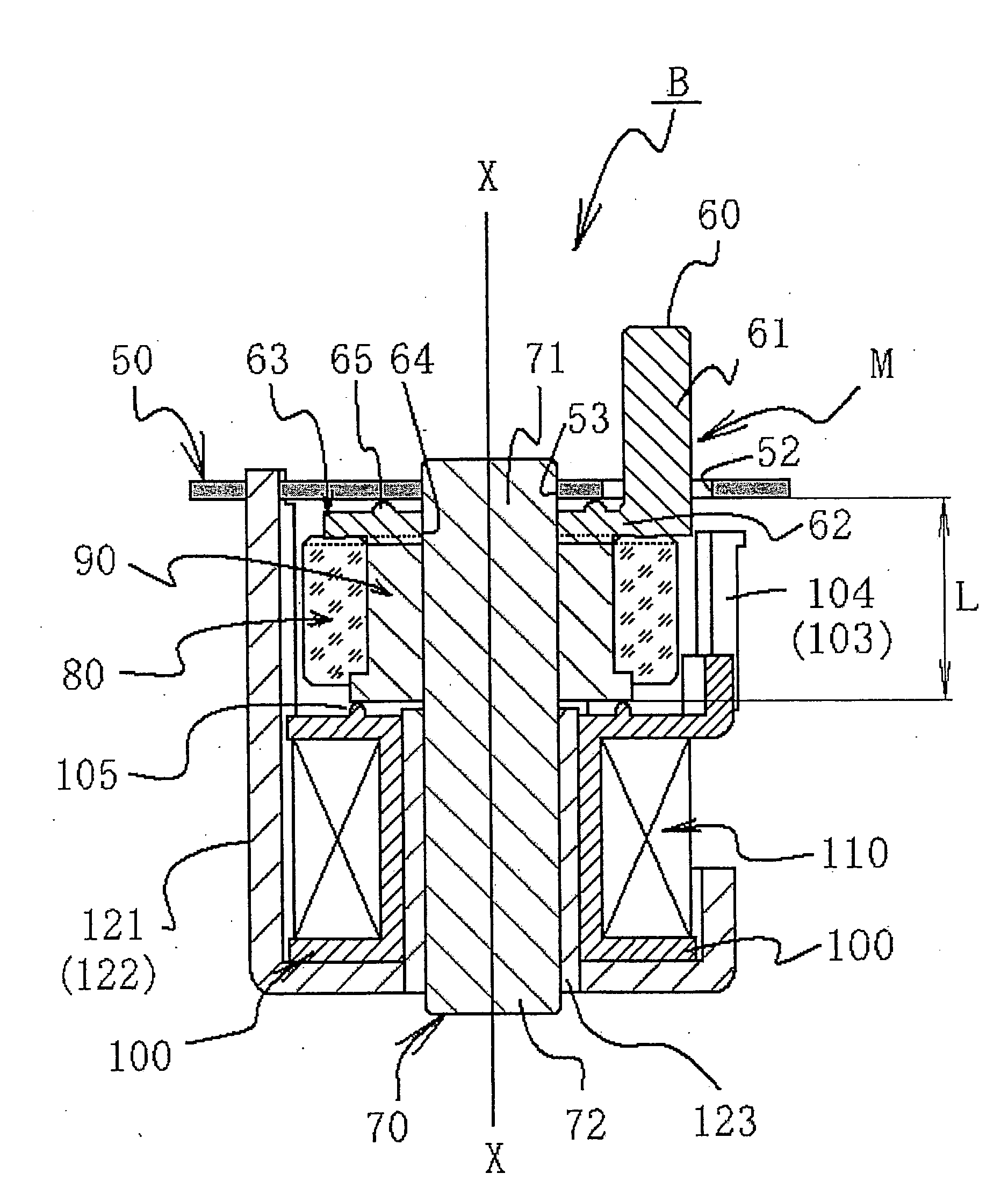
[0043]The exemplary embodiments of FIGS. 14A and 14B include a supporting structure of a magnet rotor in association with the invention. First, a theory of the supporting structure of the magnet rotor in association with the invention will be described with reference to FIG. 14A. The magnet rotor includes: a pair of upper and lower rotor supporting members 50, 100; a permanent magnet 80; a rotary shaft 70; and a driving arm 60. The permanent magnet 80, rotary shaft 70 and driving arm 60 are assembled into a rotor assembly M. In FIG. 14A, the permanent magnet 80 is configured so as to have a hollow, cylindrical shape. In the center of the permanent magnet, a shaft bore 80a is provided in which the rotary shaft 70 is fitted.

[0044]A base end portion of the driving arm 60 is fitted in the rotary shaft 70 by the following method. A first fitting part 80b composed of slotted concave parts (82 and 83 in FIG. 7), is formed in an upper end face of the permanent magnet 80. In the driving arm ...


PUM


Abstract

An electromagnetic device includes a magnet rotor having a rotary shaft and a stator having an excitation coil configured to apply a rotation force to the rotor. The magnet rotor includes a hollow cylindrical permanent magnet, a rotary shaft disposed in a hollow space portion of the permanent magnet, and a driving arm that rotates around the rotary shaft integrally with the permanent magnet. The magnet and driving arm are reliably secured, not easily separated during use, and includes a structure that facilitates machining and assemble.

Description

BACKGROUND OF THE INVENTION AND RELATED ART STATEMENT[0001]The present invention relates to an optical apparatus for an image pickup system such as a video camera or still camera, a projection system such as a projector or a rear-projection TV, and the like. More specifically, it relates to a light quantity-control device for regulating the quantity of light in association with the optical apparatus and a magnet rotor used as a driving power source for the light quantity-control device.[0002]In general, a light quantity-control device incorporated in an optical apparatus, i.e., camera and projector devices, is widely used as a shutter device or a light-limiting device. Such devices have a frame substrate (bottom board) placed at a midway position in an optical path and a thin plate-shaped blade member openably mounted on the frame substrate, wherein the shutter device opens and closes the blade member thereby adjusting the quantity of light passing therethrough or cut the optical pa...

Claims


Application Information

Patent Timeline
IPC IPC(8): H02K37/14H02K1/12
CPCH02K1/243H02K1/2733H02K37/14H02K7/14H02K1/2793H02K1/2795
Inventor NAGANUMA, HIROAKIKUSUNOKI, TOKURO
Owner NISCA KK
Why Eureka
Try Eureka