Method and apparatus for hip replacement

a hip joint and hip replacement technology, applied in the field of medical methods and equipment, can solve the problems of affecting the quality of hip joint implantation, so as to improve the quality, reliability, and compatibility of the implantation system

Inactive Publication Date: 2012-05-24
IHIP SURGICAL LLC
View PDF43 Cites 47 Cited by
  • Summary
  • Abstract
  • Description
  • Claims
  • Application Information

AI Technical Summary

Benefits of technology

[0007]In accordance with some embodiments disclosed herein, various systems, components, and methods of use and surgery are provided to enhance the quality, reliability, and compatibility of implantation systems. These apparatuses and methods can be utilized for various types of implantation systems and methods of surgery, site and system preparation, and implantation. For example, embodiments of apparatuses disclosed herein for joint replacement may be used in joints of the human body. Embodiments of the methods disclosed herein

Problems solved by technology

However, such techniques result in substantial dissection and disruption of muscles and tissues around the hip joint.
The substantial disruption of the tissues creates risk of dislocation and can require months for rehabilitation and healing.
However, many existing minimally invasive techniques still involve substantial disruption of the soft tissue envelope around the hip joint, including the tissue disruption required to create space in which to place and fit a prosthetic femoral neck and head between the femur and the acetabulum.
Moreover, many existing techniques have failed to adequately address the problem of numerous trial reductions and dislocations often required to achieve proper fit of the prosthetics which not only causes additional disruption to the tissues, but also consumes valuable time.
Many of these techniques involve significant rotation, dislocation and damage to the bone and surrounding tissue, including muscles, ligaments, blood vessels, and nerves.
Sometimes, the leg must be bent up to 60 degrees, with twisting and pinning of the leg, which in roughly 6% of procedures, results in a new bone break during the implantation procedure.
In some instances, insertion of hip implant components through two incisions involve sig

Method used


Image

  • Method and apparatus for hip replacement
  • Method and apparatus for hip replacement
  • Method and apparatus for hip replacement

Examples


Embodiment Construction

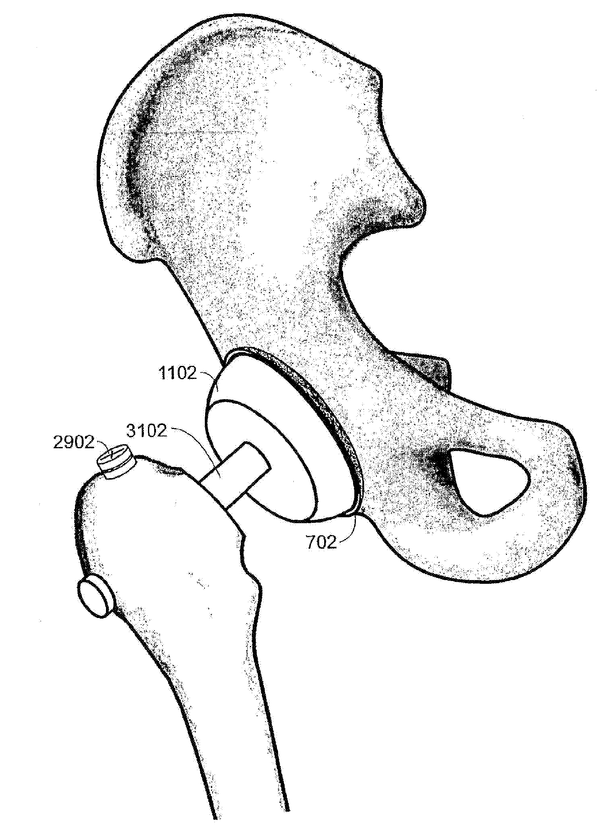
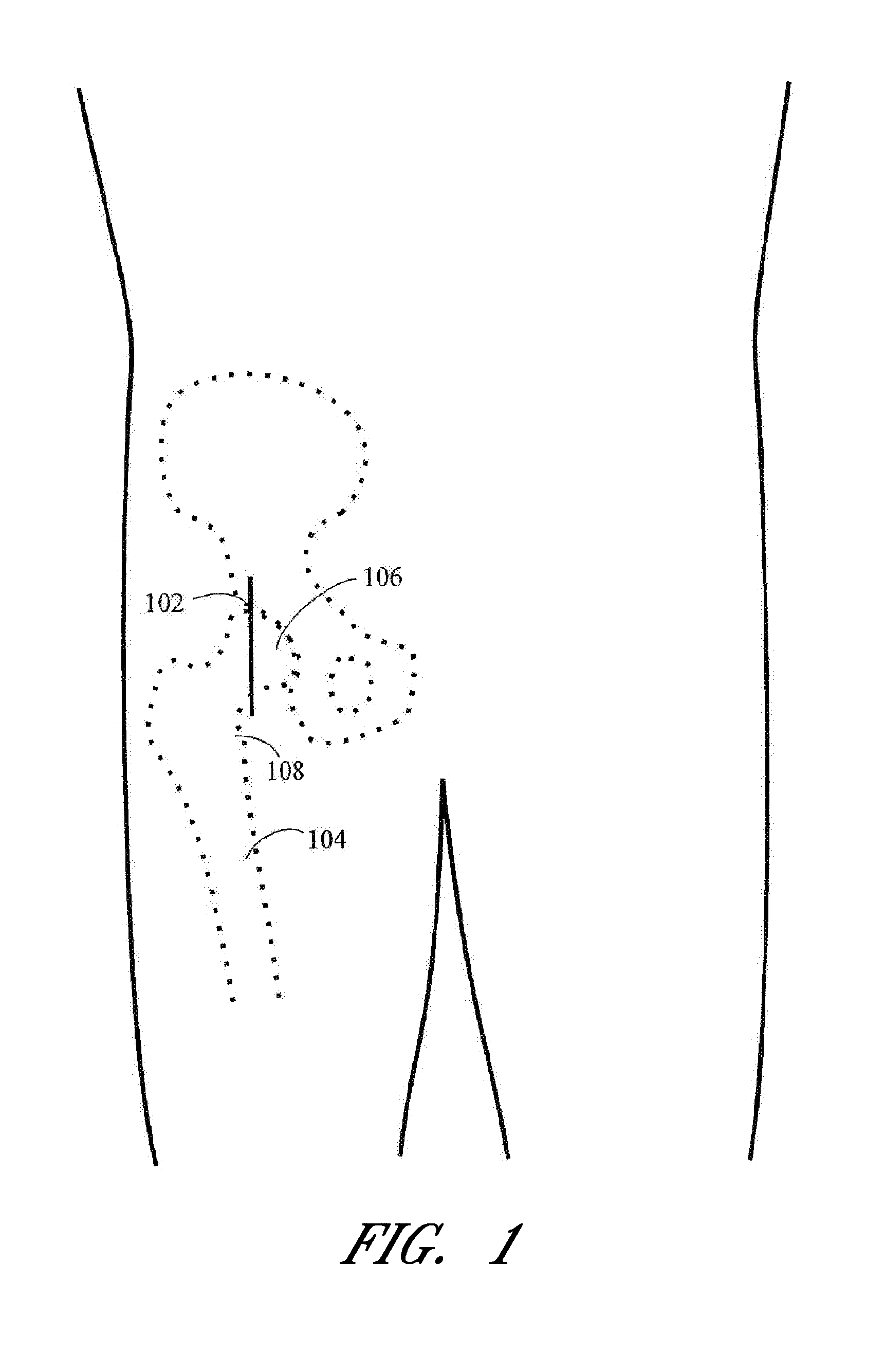
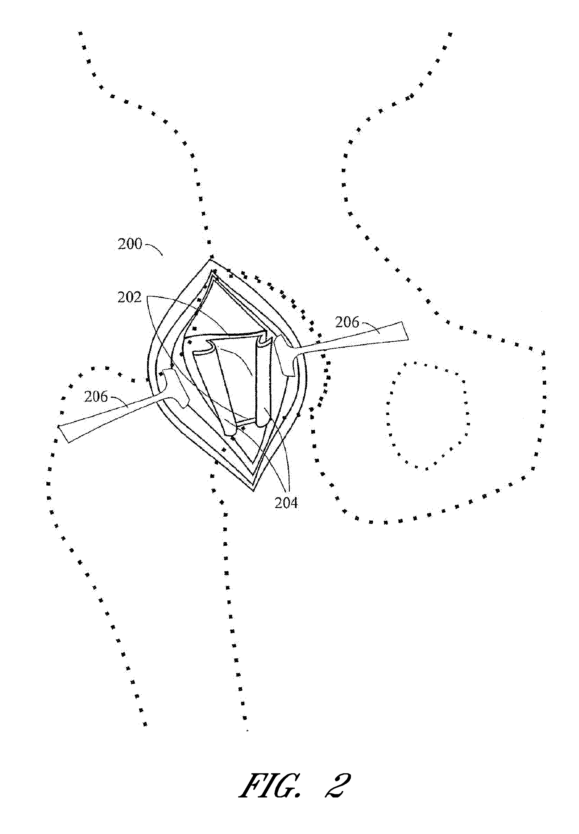
[0227]While the present description sets forth specific details of various embodiments, it will be appreciated that the description is illustrative only and should not be construed in any way as limiting. Additionally, it is contemplated that although particular embodiments of the present inventions may be disclosed or shown in the context of hip surgeries, such as total hip arthroplasty or hemiarthroplasty, such embodiments can be used in other surgical techniques and devices. Furthermore, various applications of such embodiments and modifications thereto, which may occur to those who are skilled in the art, are also encompassed by the general concepts described herein.

[0228]Embodiments of the methods, systems, components, and devices disclosed herein can be used for various joints of the body, such as the shoulder, hip, and the like. As discussed in the above-noted publications, joint replacements for the hip are common and have several factors that can be considered when designin...


PUM


Abstract

Methods and apparatus for orthopedic replacement of the hip through three incisions with a modular prosthetic system assembled in vivo while substantially preserving muscles and soft tissues around the hip joint resulting in reduced healing time and decreased risk of dislocation. A prosthetic femoral stem is inserted into the femur. A prosthetic femoral neck is inserted from a point along the side of the patient's body and into the side of the femur and through a lateral bore in the prosthetic femoral stem to join the prosthetic femoral head. The methods and apparatus include structures and techniques for fixing or enhancing interconnection of implant components, such as by increasing the interconnection in an interference fit with one or more tapers, threads, and/or cooling of components prior to assembly.

Description

CROSS-REFERENCE TO RELATED APPLICATIONS[0001]This application is a continuation-in-part of U.S. application Ser. No. 13 / 049,619, filed Mar. 16, 2011, which is a divisional application of U.S. application Ser. No. 12 / 518,081, filed Jun. 5, 2009 and issued as U.S. Pat. No. 8,029,573, which is a U.S. National Phase application of PCT / US2006 / 046795, filed in English on Dec. 7, 2006 and published as WO 2008 / 069800 A1 on Jun. 12, 2008, each of which are incorporated by reference in their entireties herein.BACKGROUND[0002]1. Field[0003]Embodiments of the present invention relate to medical methods and apparatus, and more particularly to a method and apparatus for minimally invasive total- or hemi-hip arthroplasty.[0004]2. Description of the Related Art[0005]Early methods and apparatus for performing total hip replacement generally involve a long incision and with open visualization of the trochanteric region of the femur, the femoral head and the acetabulum. However, such techniques result...

Claims


Application Information

Patent Timeline
IPC IPC(8): A61F2/32
CPCA61B17/164A61F2310/00203A61B17/1668A61B17/1684A61B17/1717A61B17/1721A61B17/175A61B17/7266A61B17/7283A61B17/86A61B2017/924A61F2/30749A61F2/32A61F2/34A61F2/3609A61F2/367A61F2/4609A61F2002/30013A61F2002/30332A61F2002/30405A61F2002/30433A61F2002/30448A61F2002/30451A61F2002/30476A61F2002/30507A61F2002/30594A61F2002/30604A61F2002/30617A61F2002/30673A61F2002/30738A61F2002/30787A61F2002/30794A61F2002/30797A61F2002/30894A61F2002/30904A61F2002/30906A61F2002/30909A61F2002/3401A61F2002/3404A61F2002/3412A61F2002/3446A61F2002/3611A61F2002/3625A61F2002/3631A61F2002/365A61F2002/3652A61F2002/369A61F2002/4629A61F2002/4636A61F2002/4668A61F2002/4681A61F2220/0025A61F2220/0033A61F2220/0041A61F2220/005A61F2220/0058A61F2250/0024A61F2310/00017A61F2310/00023A61F2310/00029A61F2310/00131A61F2310/00179A61B17/1666A61B17/888A61F2002/30011A61F2002/3079A61F2002/3403A61F2002/4635A61F2/3662
Inventor PODOLSKY, ANATOLGARBUZOV, YURI
Owner IHIP SURGICAL LLC
Why Eureka
Try Eureka