Method for detecting signal and estimating symbol timing

a symbol timing and signal detection technology, applied in multi-frequency code systems, digital transmission, amplitude demodulation, etc., can solve the problems of missing signals, inability to calculate cross correlation, additional power consumption and waste of frequency bandwidth, etc., to ensure the correctness of timing estimation, ensure the effect of timing estimation and sufficient length for cross correlation computation

Inactive Publication Date: 2006-06-29
IND TECH RES INST
View PDF13 Cites 49 Cited by
  • Summary
  • Abstract
  • Description
  • Claims
  • Application Information

AI Technical Summary

Benefits of technology

[0011] The significant feature of the present invention is to use the ending determination mechanism of the short preamble of the input signal to find a sliding window for timing estimation in order to guarantee the correctness of timing estimation. Furthermore, the long preamble, after the coarse frequency compensation, can have a longer preamble code or guard interval plus the long preamble code for cross correlation computation. Because the frequency is coarsely compensated and the length for cross correlation computation is sufficiently long, thereby only taking the sign bit for computation. In such a way, a good computation result can be obtained. Therefore, the present invention uses a signal detection mechanism to ensure the correctness of the long preamble timing estimation. This not only reduces the error rate of the timing estimation, but also finds out the correct boundary of the OFDM symbol easily.

Problems solved by technology

If the transmitted OFDM signal is undetected, the miss of the signal will occur.
This leads to the additional power consumption and waste of frequency bandwidth.
Without the coarse frequency compensation, the length of cross correlation computation cannot be too long because the reverse vector will appear when the rotation exceeds π, and this reduces the correctness of timing estimation.
But the short preamble is prone to incorrect estimation due to its shortness.
It is also prohibitively time-consuming.
However, because a communication system may have many noise interferences and other factors, the system using a single value of the short preamble as the unit may have high probability of signal misses and false alarms.

Method used


Image

  • Method for detecting signal and estimating symbol timing
  • Method for detecting signal and estimating symbol timing
  • Method for detecting signal and estimating symbol timing

Examples


Embodiment Construction

[0028]FIG. 4 shows a schematic view of a receiver structure of an OFDM system. Referring to FIG. 4, the receiver comprises two analog-to-digital converters 11, a signal detection circuit 42, a frequency estimation circuit 44, a complex number multiplier 43, and a symbol synchronization processing circuit 45. The signal, after passing A / D converter 11, is split for frequency estimation and signal detection. After the coarse frequency compensation, the timing estimation can be performed so that the subsequent timing estimation can be more correct.

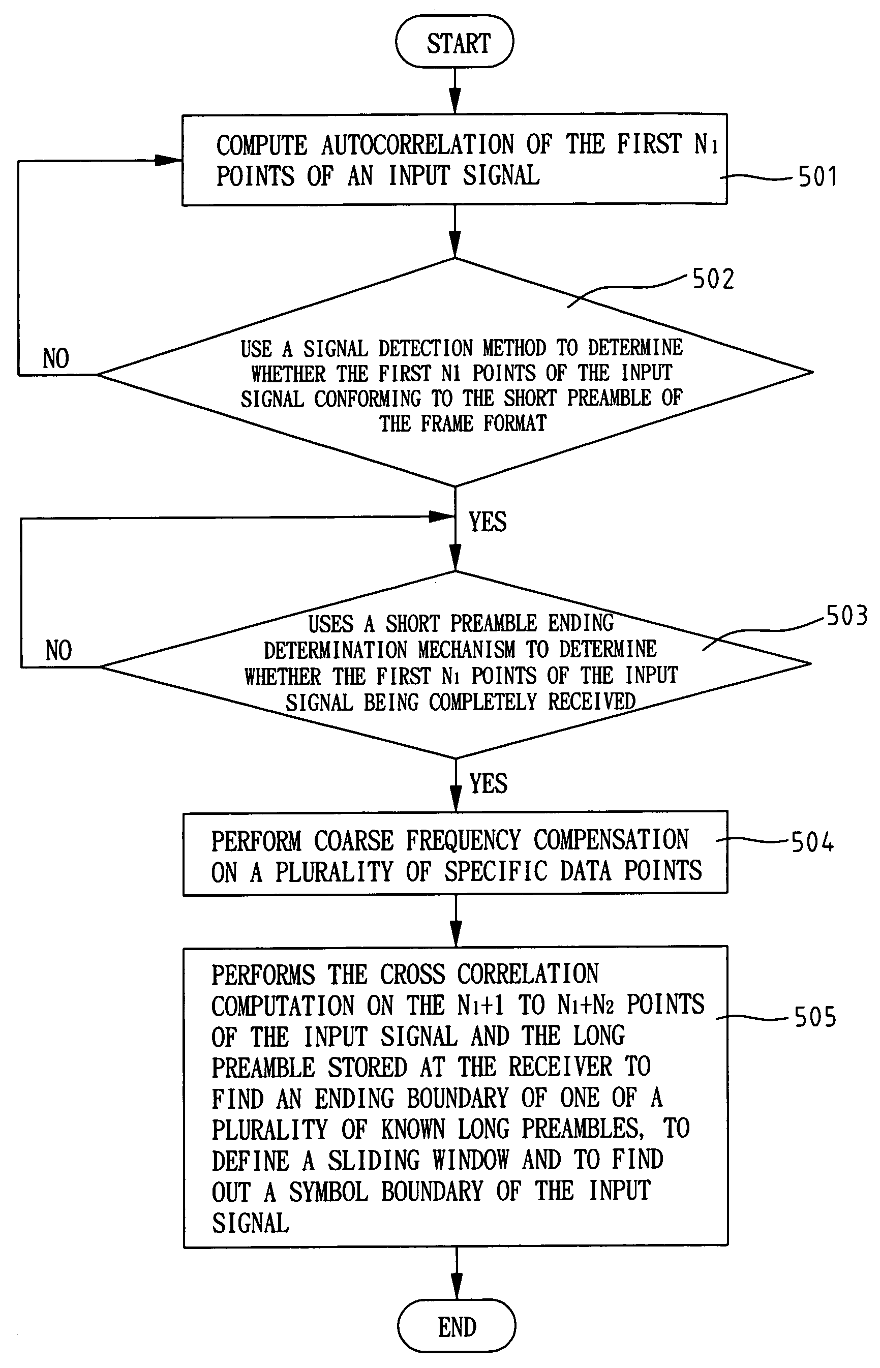
[0029]FIG. 5A shows a method of signal detection and timing estimation according to the present invention. As shown in FIG. 5A, the method of signal detection and timing estimation is applicable to a receiver of an OFDM system. The OFDM system uses a communication code frame format. Each transmit frame conforming to the format includes a short preamble, a long preamble, and a plurality of OFDM symbols. The short preamble includes a plurality...


PUM


Abstract

A method for detecting signal and estimating symbol timing is provided. The method is applicable to the receiver in an OFDM system. The method uses the autocorrelation of the short preamble of input signals to detect signals, and performs the coarse frequency offset compensation at the same time. Then, the end of the short preamble for the input signals is detected by the signal detection. The compensated signals are cross-correlated with the portion of the long preamble or that of guard interval together with the long preamble. In addition, the method uses the information for the end of the short preamble to find out a range of the sliding window for estimating symbol timing. In such a manner, the method can make sure of the accuracy for the symbol timing.

Description

FIELD OF THE INVENTION [0001] The present invention generally relates to an orthogonal frequency division multiplex (OFDM) signal, and more specifically to a method for OFDM signal detection and symbol timing estimation. BACKGROUND OF THE INVENTION [0002] The OFDM technologies can be used in high speed transmission and solving the multi-path interference caused by neighboring symbols. Therefore, OFDM technologies are used in digital audio broadcasting (DAB) and the European standard digital video broadcasting (DVB) system. In addition, OFDM technologies are also the choice of modulation for using in the non-regulated frequency range and the Hiperlan2 of European Telecommunications Standard Institute (ETSI). For example, the highest transmission speed of IEEE 802.11a has reached 54 Mbps. [0003] In the wireless communication system, a receiver must include a signal detection mechanism because the arrival of real system signals is unknown in advance. Signal detection is the first step ...

Claims


Application Information

Patent Timeline
Patent Type & Authority Applications(United States)
IPC IPC(8): H04K1/10H04L27/06
CPCH04L27/2613H04L27/2662H04L27/2659H04L27/2675
Inventor LAI, KO-YINTSAI, WAN-JENTING, HUNG-JUA
Owner IND TECH RES INST
Why Eureka
Try Eureka