Flash Drive With Swivel Cover

a technology of flash drives and swivel covers, which is applied in the direction of electrical apparatus casings/cabinets/drawers, coupling device connections, instruments, etc., can solve the problems that embodiments would not share the benefits of substantially semi-cylindrical structures and the benefits of midpoint locations, so as to facilitate the manufacturing of swivel covers and minimize material costs , the effect of minimal length

Inactive Publication Date: 2011-09-29
SUPER TALENT TECH CORP
View PDF15 Cites 30 Cited by
  • Summary
  • Abstract
  • Description
  • Claims
  • Application Information

AI Technical Summary

Benefits of technology

[0012]In accordance with an embodiment of the present invention, the recessed ring-shaped grooves are located approximately midway between a rear wall portion of the housing and a front edge of the plug connector, whereby when the swivel cover is in the closed position, the end wall of the swivel cover is spaced from the front edge of the plug connector by a minimal offset distance (e.g., 0.25 inches or less, so long as it provides a clearance that is not blocking the rotation path of the swivel cover), and when the swivel cover is manually rotated 180° from the closed position, the end wall of the swivel cover is spaced from the rear wall portion by approximately the same minimal offset distance (e.g., 0.25 inches or less). Locating the recessed ring-shaped grooves in this manner facilitates manufacturing the swivel cover with a minimal length, thus minimizing material costs, and this approach also minimizes the overall length of the flash device when the swivel cover is rotated 180° from the closed position. In alternative embodiments, the recessed ring-shaped grooves may be located anywhere along the length of the housing, but such alternative embodiments would not share the benefits of the midpoint location.
[0013]In accordance with another embodiment of the present invention, the end wall of the swivel cover is formed as a substantially semi-cylindrical structure that extends between the upper cover wall and the lower cover wall. Note that it is necessary to bend the swivel cover to separate the end portions of the upper and lower cover walls in order to provide sufficient clearance to mount the ring-shaped protrusions in the recessed ring-shaped grooves. By forming the swivel cover with a substantially semi-cylindrical end wall, the required bending / spreading of the upper and lower cover walls during assembly is achieved without risking permanent deformation of the swivel cover. In alternative embodiments, the end wall may have a rectangular or other angled shape, but such alternative embodiments would not share the benefits of the substantially semi-cylindrical structure.
[0014]In accordance with another embodiment of the present invention, locking structures are disposed on the ring-shaped protrusions and in the ring-shaped grooves that served to resist rotation of the swivel cover relative to the housing when the swivel cover is in either of the closed position or the fully open position. That is, because the ring-shaped protrusions extend perpendicular to the upper / lower cover walls and are received in the recessed ring-shaped grooves, the present invention facilitates the addition of simple snap-locking structures that serve to hold the swivel cover in the closed position while minimizing the length and material costs of the swivel cover and the housing in comparison to conventional swivel-type devices, and thus reducing manufacturing costs. In a specific embodiment, the locking structures are implemented by pairs of snap slots are defined on the peripheral edge of the ring-shaped protrusions, and pairs of snap tabs are disposed at the bottom of the ring-shaped grooves, and the swivel cover is biased against the housing such that the peripheral edges of the ring-shaped protrusions ride along the snap tabs until the snap tabs are aligned with and enter into the snap slots. By positioning the snap tabs such that the snap slots engage the snap tabs when the swivel cover is in either of the closed position or opened position, the locking structure serves to resist undesirable exposure of the plug connector during idle periods, thereby extending the operating life of the flash device. In alternative embodiments, the structures on which the snap tabs and snap slots are formed may be reversed (e.g., the snap tabs may be formed on the swivel cover) or other locking structures (e.g., snap tabs that extend from side walls of the ring-shaped protrusions) may be used.
[0015]In accordance with some of the disclosed specific embodiments, the swivel cover is attached to the housing such that the ring-shaped protrusions are securely slidably biased (pushed into) the ring-shaped grooves. The biasing force may be provided by the spring-type resilience of the swivel, or by connection structures that are located inside the circular openings defined in the swivel cover, and are entirely disposed between the outermost surfaces of the upper and lower cover walls. By attaching the swivel cover to the housing in this manner, the assembly facilitates the implementation of simple locking structures, such as those described above, and also facilitates reliable connection of the swivel cover to the housing without the need for a hinge protuberance or other structure that extends outside of the outmost surfaces of the upper / lower cover walls, thereby providing a sleeker and more aesthetically pleasing flash device. In accordance with some of the disclosed specific embodiments, connection structures are implemented in the form of rivet caps that are mounted inside the circular openings defined in the swivel cover and extend into rivet openings defined in the upper / lower housing walls. The rivet caps are secured to the housing by way of snap arms or by any other securing means (e.g., ultrasonic welding). In one specific embodiment the rivet caps are formed from transparent or translucent (light permissive) material (e.g., clear plastic) such that light from an activated light source (e.g., an LED) disposed inside the housing is visible through the rivet cap when the flash device is in operation. In accordance with other specific embodiments, the upper / lower housing walls include integrally molded circular attachment structures that are disposed inside of the recessed ring-shaped grooves and extend into the circular openings defined in the swivel cover. The circular attachment structures are either snap-coupled, ultrasonically welded or otherwise disposed to rotatably secure the swivel cover to the housing. In some specific embodiments, a separate light pipe or other viewing structure is disposed in the upper or lower housing wall to display light from an activated light source (e.g., an LED) disposed inside the housing during operation.
[0016]In accordance with alternative embodiments of the present invention, the housing is provided either as a two-part housing structure or as a tubular housing structure. In the embodiments employing a two-part housing structure, a PCBA is mounted onto a lower housing portion, and then an upper housing portion is mounted onto and secured (e.g., by ultrasonic welding or snap-coupling) over the lower housing structure. An advantage of the two-part assembly is that the PCBA may be securely held between support structures integrally molded on the inside surfaces of the upper and lower housing portions. In the tubular housing embodiments, a PCBA is inserted through a front or rear opening of a tubular housing, and then secured by way of one or more end caps that are attached (e.g., by ultrasonic welding or snap-coupling) over one or both ends of the tubular housing. An advantage of the single-piece housing arrangement is that the distance between the upper and lower housing walls is reliably set during the molding process, thereby simplifying the assembly process.
[0017]In accordance with additional alternative embodiments of the present invention, various features are implemented to further enhance the value and novelty of the flash drive. First, although the exemplary embodiments provided herein include the use of Universal Serial Bus (USB) plug connectors, other plug connector types may also be used. Second, although the exemplary embodiments provided herein include the use of multi-level cell (MLC) packages, other package types such as a Chip-On-Board (COB) package or a Slim Printed Circuit Board Assembly (Slim PCBA) package may also be used. Further, the end wall of the C-shaped swivel cover may be modified to define a pair of key-chain openings that facilitate attaching a key chain or other connector to the flash device. Finally, parallel raised protrusion stripes may be disposed on the side wall portions of the housing to facilitate the manual opening / closing operations (i.e., to improve a user's grip on the device housing in order to prevent his / her fingers from slipping). In other alternative embodiments, the upper and lower housing walls of the housing and upper and lower cover walls of the C-shaped swivel cover are rectangular or other angled shapes (i.e., not curved), but such alternative embodiments would not share the benefits of the substantially curved housing and swivel cover structure.

Problems solved by technology

In alternative embodiments, the recessed ring-shaped grooves may be located anywhere along the length of the housing, but such alternative embodiments would not share the benefits of the midpoint location.
In alternative embodiments, the end wall may have a rectangular or other angled shape, but such alternative embodiments would not share the benefits of the substantially semi-cylindrical structure.

Method used


Image

  • Flash Drive With Swivel Cover
  • Flash Drive With Swivel Cover
  • Flash Drive With Swivel Cover

Examples


Embodiment Construction

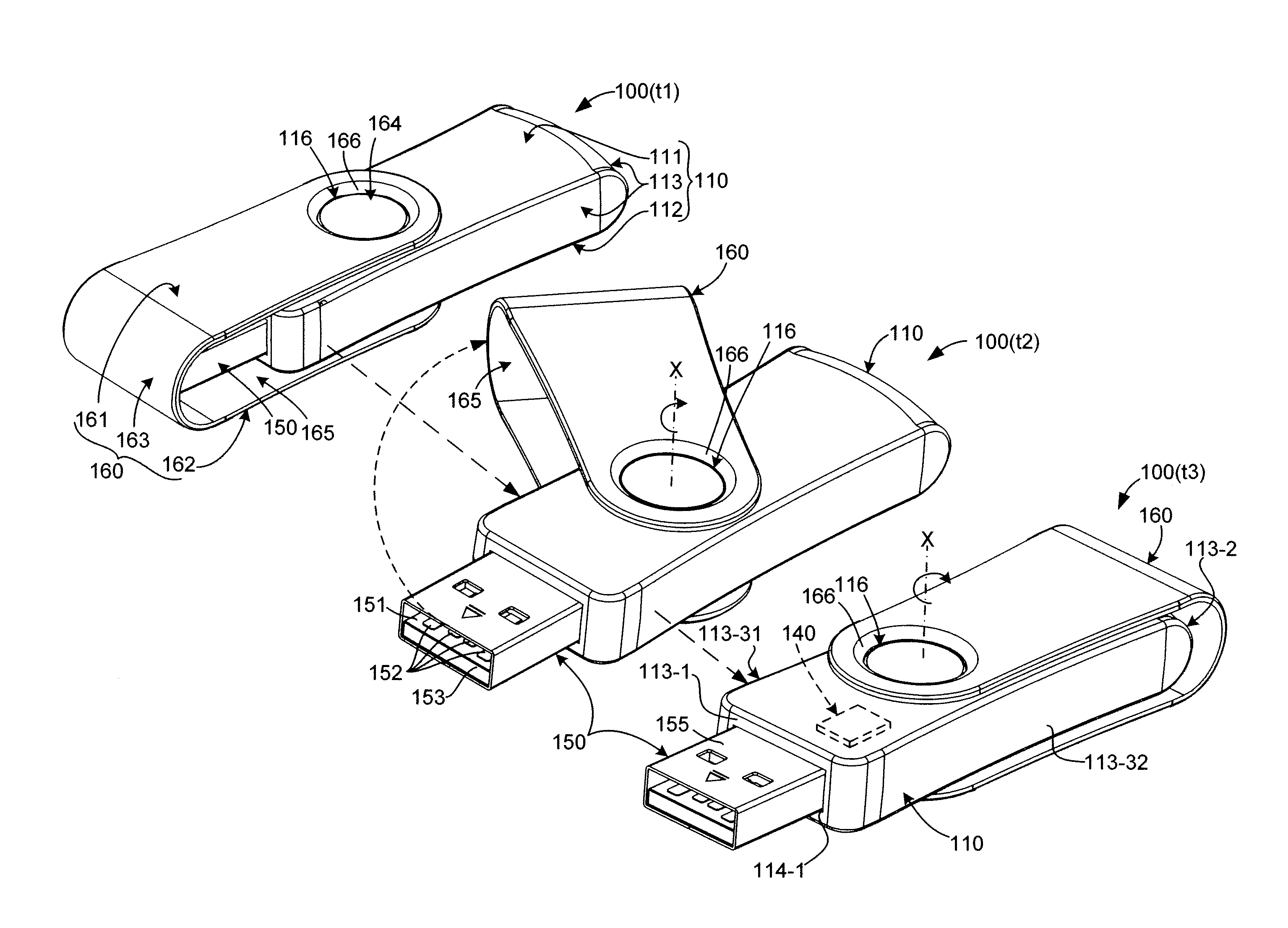
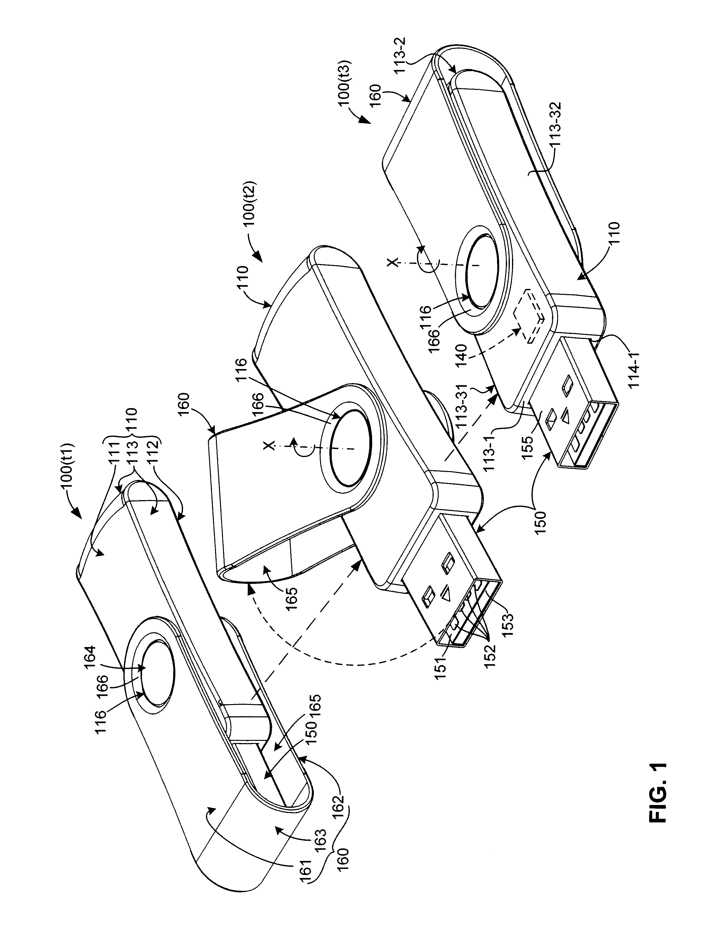
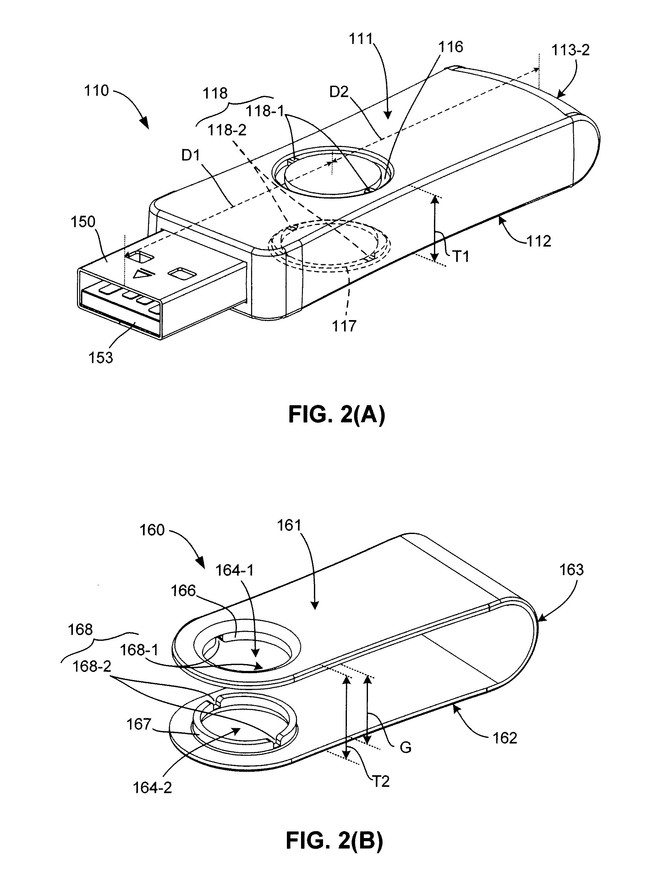
[0038]The present invention relates to an improvement in flash memory devices such as USB flash drives. The following description is presented to enable one of ordinary skill in the art to make and use the invention as provided in the context of a particular application and its requirements. As used herein, directional terms such as “upper”, “upwards”, “lower”, “downward”, “front”, “rear”, are intended to provide relative positions for purposes of description, and are not intended to designate an absolute frame of reference. In addition, the phrases “integrally connected” and “integrally molded” is used herein to describe the connective relationship between two portions of a single molded or machined structure, and are distinguished from the terms “connected” or “coupled” (without the modifier “integrally”), which indicates two separate structures that are joined by way of, for example, adhesive, fastener, clip, or movable joint. Various modifications to the preferred embodiment wil...


PUM


Abstract

A swivel-type portable flash device includes a C-shaped swivel cover that rotates (swivels) relative to a housing between an open position in which a plug connector is exposed for insertion in a host system, and a closed position in which the plug connector is covered and protected by the swivel cover. The swivel cover is permanently rotatably connected to the housing by way of ring-shaped protrusions that are movably engaged inside corresponding recessed ring-shaped grooves formed in upper/lower walls of the housing, whereby the swivel cover is manually rotatable relative to the housing between the opened and closed positions. The swivel cover also includes locking structures (e.g., locking notches) disposed on the ring-shaped protrusions, and the housing includes second locking structures disposed in the recessed ring-shaped grooves, where the first locking structures operably engage the second locking structures to prevent rotation of the swivel cover when the plug connector is in the closed position.

Description

RELATED APPLICATIONS [0001]This application is a continuation-in-part (CIP) of co-pending U.S. patent application for “Universal Serial Bus (USB) Flash Drive Having Locking Pins and Locking Grooves for Locking Swivel Cap”, Ser. No. 11 / 929,857, filed Oct. 30, 2007.BACKGROUND OF THE INVENTION[0002]1. Field of the Invention[0003]The present invention relates generally to the field of portable flash drives and particularly to portable drives with swivel caps and methods for manufacturing thereof.[0004]2. Description of the Related Art[0005]Universal serial bus (USB) flash drives represent one type of portable flash devices that are available in various shapes and forms. Conventional pen-type USB flash drives typically include a flash memory device and a controller that are disposed in a protective housing, and are operably connected to a USB plug connector that extends from a front end of the housing. Conventional pen-type USB flash drives typically include a removable cap (cover) that ...

Claims


Application Information

Patent Timeline
Patent Type & Authority Applications(United States)
IPC IPC(8): H01R13/447
CPCG06K19/07732H05K5/0278G07C9/00087G07C9/257
Inventor NI, JIM CHIN-NANMA, ABRAHAM C.
Owner SUPER TALENT TECH CORP
Why Eureka
Try Eureka